Following is some general information on the development and evolution of the "motor torpedo boat" in the years leading up to and during the second world war.
If you are interested specifically in ELCO 77 foot PT boats click here and here; for information about models of ELCO 77 foot boats, go here.
The story of Motor Torpedo Boat Squadron Three (RON 3), "The Expendables".
If interested in the ELCO 80 foot boats go here; for models of early 80 foot ELCO go here and for model of late versions go here.
Brief notes on John Kennedy's two PT Boats, PT 109 and PT 59.
Information on the Higgins 78 foot boats is here; and models of Higgins PTs here.
For a brief discussion of the differences between the ELCO PTs and the Higgins PTs go here.
Notes on the evolution of the armament of PT boats here.
Additional information on building the 1:32 scale series with photos of the construction of guns and torpedoes and of the completed models can be found in the generic modeling tips and photos section.
The US navy had developed "torpedo boats" in the last decades of the 19th century in response to the development of the self-propelled mobile torpedo. These boats were, for the most part, steam powered, steel hulled vessels of about 100 to 200 tons displacement and about 140 to 160 feet long, generally with narrow beam. They looked very much like the later "destroyers" of WW1 and were evolving in that direction by the first decade of the 20th century.
During WW1, submarine-based torpedo warfare became increasingly important, and anti-submarine vessels evolved in response to the submarine threat. Although torpedoes were still carried on surface vessels in addition to traditional cannon, they were largely secondary weapons on capital ships and the class of dedicated torpedo boats largely disappeared. The thinking and strategic planning of most of the world's naval leaders remained bound to gunnery and capital ships. Ships grew larger to support larger batteries for ship to ship combat and onshore bombardment. Smaller ships served to protect the capital ships from submarine and small vessel attack.
By the 1920s, however, development of the internal combustion engine led to rapid progress in development of aviation and a similar interest grew in the new gasoline engines for use in boats. Racing motor boats powered by the new engines caught the fancy of racers and the public. Engines improved and hull design favored hard chined planing hulls that rode the surface of the water rather than running deeper as the older displacement hulls did. Britain in particular encouraged development of experimental small, fast, gasoline powered vessels for operation close to shore in the English Channel. T.E.Lawrence, during his post war quest for anonymity, worked for a time with a group developing gasoline engines for such vessels.
In the United States fast racing boats were also used for running liquor along the coast, often shuttling between a large vessel lying far off shore and the off-loading points in secluded or unguarded locations on the shore. These boats relied on their speed to evade or avoid pursuit.
By the 1930s, with the prospect of war looming, English research into development of fast gasoline powered craft for operation in the Channel accelerated. Hubert Scott-Paine, an English entrepreneur, aircraft developer, and boat racer in the 1920s began building fast, hard-chine speedboats in the mid 1930s and his boats became known for superior speed and performance. His designs for similar boats adapted for anti-submarine and coastal warfare were soon purchased by the Admiralty.
During these same times, the US Navy became interested in developing small "motor torpedo boats". Not surprisingly, the navy attempted to develop designs for such boats in-house, but the process was slow and not very successful. There were a series of experimental designs for the boats beginning in the 1920s and 1930s and gradually design specifications evolved to the point that the process could be put up for outside bids. Toward the end of this development process, the US Navy specified that the boats should carry four torpedo tubes of USN design launching the 21" diameter torpedo (Mark 14) used in submarines and destroyers. The Navy also specified a maximum tonnage of 50 tons so the boats could be transportable by ship (weight limited by crane capacity) and a speed of greater than 30 knots.
In 1939 the U.S Navy arranged for the Electric Launch Company (ELCO)) to purchase one of Scott-Paine's designed 70 foot British Power Boat as a template for American production of these boats under licence. This particular hull was later assigned the number PT 9 around the time of the "Plywood Derby", but was deemed too short to carry the four torpedoes required by the Navy specifications. ELCO build a copy of this hull as the PT 10. Neither of these boats participated in the Plywood Derby.
The Scott-Paine design was very influential in the design of the larger 77 foot ELCO PT boat (PT 20) which also partipated in the Plywood Derby and was the first design awarded a Navy contract in 1941. For 24 boats. PT 20 was later commissioned and armed and served during the war.
In 1941, the navy held the "Plywood Derby", which consisted of open sea trials of multiple experimental PT boats, including Navy designs as well as boat designed and built by external contractors. These trials led to the aproval of the 77 foot ELCO design and an order for 24 boats, approval of the Higgins design as modified to 78 feet length, and approval of the Huckins design (72 feet). The ELCO boats and the Higgins boats were the only versions of these early PT designs to enter large scale production and see combat. There were only a few (18) of the Huckins boats built and they were largely used for training.
ELCO would build another 24 boats of 77 feet length, with some modification of this second version as described below. At Navy request, ELCO also designed a boat of 80 feet length to carry more armament. The ELCO 80 foot PT boat became the most numerous PT boat in service.
Most of the ELCO designed boats served in the Pacific theater, with a small number used in the English Channel and Mediterranean Sea. Approximately half the Higgins boats served in the Mediterranean Sea and English Channel with the other half serving in the Pacific and Aleutians. A number of Higgins boats were also transferred to the USSR at the time of commissioning. Huckins boats were assigned to the training squadron in Melville Rhode Island, the Panama Canal zone, and Hawaii. None of the Huckins boats saw combat.
In 1940 the Navy Department decided that PT boats would not be commissioned individually but would operate in squadrons (known informally as "RONs") of 12 boats each with each squadron having its own commanding officer. The officers-in-charge (boat captains) and crew members of each PT boat moved from boat to boat within their squadron, depending on availability of boats and crews and mission requirements, and the boats themselves moved from squadron to squadron as needed when squadrons were reformed due to losses.
A total of 690 PT boats were built between 7 December 1941, and 1 October 1945.
The "Plywood Derby" trials also resulted in standardization the engines of the boats to three Packard marine engines. These water- cooled gasoline engines had 12 cylinders and were derived from the earlier Packard aviation engines but were very different engines, adapted to marine use and heavier than the aircraft versions which evolved separately. Despite being different engines, the PT boat engines also ran on aviation grade gasoline and put out 1200 HP each in the first version. Horsepower was gradually increased to 1500 during the war, and a final version of the Packard marine engine put out 1800 HP. These engines were used on all US PT Boats although the gearing and placement varied somewhat. They were water-cooled, supercharged, and had two spark plugs per cylinder. Exhaust exited through six exhaust ports in the transom of ELCO boats and through three underwater exhaust ports on each side of Higgins boats.
Later sections will discuss more information on the ELCO and Higgins boats. Only eighteen Huckins boats were ever built and none saw combat, so I won't say more about that class of boat. There were also around 90 or so seventy foot boats built to Vosper plans for the British in US yards and given PT hull numbers but never assigned to US Naval forces. Similarly, there were PT boat hull numbers assigned to boats transferred to the USSR during the war. PT hull numbers were assigned to a boat at the time the keel was laid and remained with the hull unless transferred to another nation or otherwise reclassified and given a new number.
By the end of the war, ELCO had built a total of 49 77 foot PT boats (PT 20 - 68) before switching over to build the 80 foot PTs (326 total made). Higgins made 199 of their 78 foot design.
Development of the 77 foot ELCO
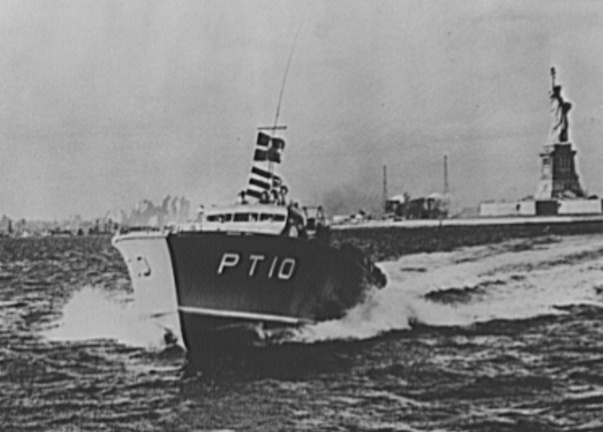
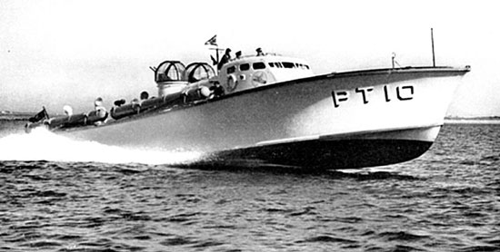
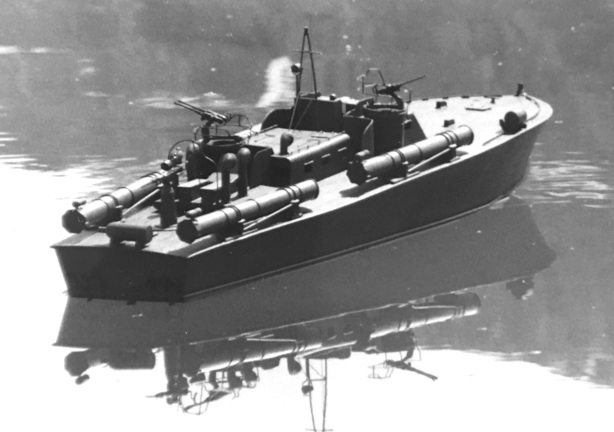
Here are two photos of PT 10, a 70 foot PT boat by ELCO that was a copy of the Scott-Paine design. You can see the four torpedo tubes and the two turrets with twin machine guns. The photo shows the plastic covering on the turrets. You can also see the yacht-like lines of the hull and cabin, both elements that made construction more difficult. The 70 foot design was deemed too small to carry the four torpedo tubes required by the Navy and no more were built. PT hull numbers up to 20 were assigned to quite variable experimental boats from the Navy designers as well as outside sources.
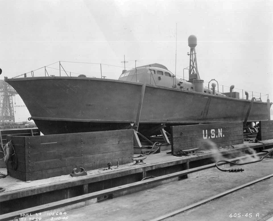
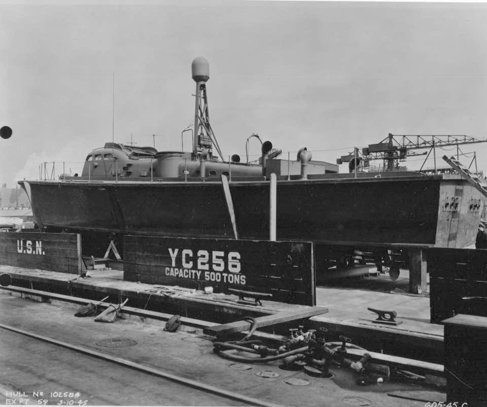
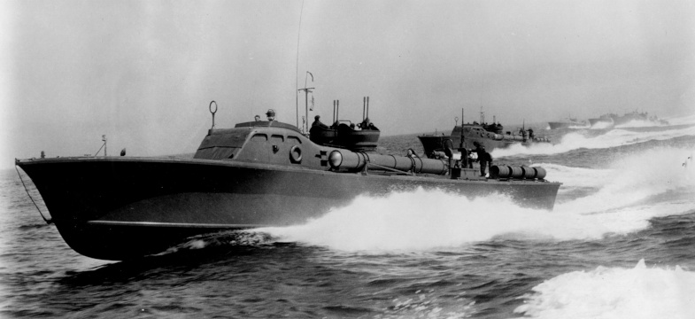
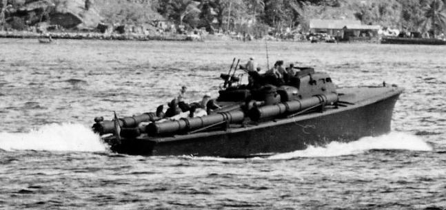
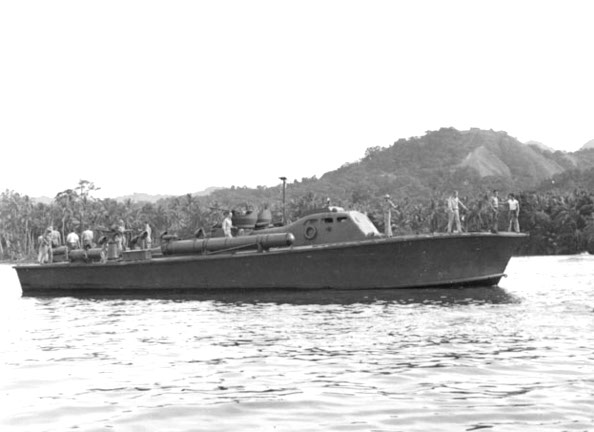
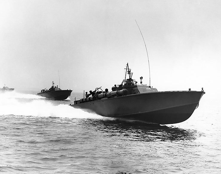
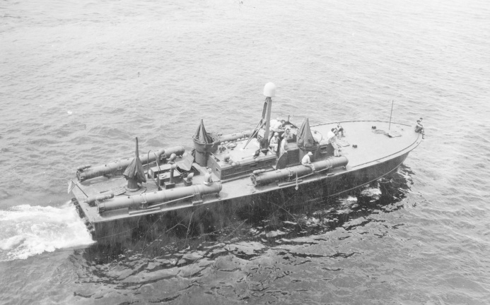
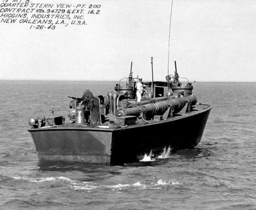
Here are a couple pictures of 77 foot ELCO boats. You can see the influence of the Scott-Paine hull in them.
The first photo is likely a publicity picture or photo from the sea trial of these boats as one man in the cockpit is wearing a fedor and the other is hatless. Notice the mast behind the cockpit has no radar and is lacking the lines and radio antenna fitted later. The cabin shape fairs into the engine room cabin smoothly and the gun turrets lack the glazing and have the higher flared sides of the late 77 boats. There are still steps on the side of the pilot house cabin to climb up and over into the cockpit. These are likely late 77 foot ELCO boats.
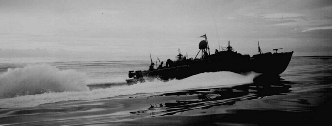
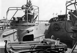
The second photo shows an early ELCO PT boat in the field You can see the abrupt change in curvature of the cabin just aft of the cockpit and the steps to climb up and over the cabin sides to enter the cockpit. The turrets lack the plexiglass covers removed by the crews and lack the shape of the later ELCO boats. The Lewis guns on the forward deck are gone and the boat has no number, probably censored out. The boat in the first picture is operating at speed enough for the hull to start planing, which happened at about 25 knots. This boat is probably lightly loaded with dummy torpedoes for this shot. Notice also the tow rope at the bow, attached to the large towing eye near the waterline and running up through a fairlead at the top. These ropes were a standard feature on all PT boats and used commonly when the boats needed a tow after engine failure or damage, or when towing other boats. The boat in the second picture floats lower in the water and is not at planing speed, although throwing a prominent "rooster tail".
The PT 20 was first-in-class of the initial 77 foot ELCO boats. It was launched March of 1940 and made its first appearance in the "Plywood Derby". After acceptance by the Navy and the issue of a contract for 24 boats, the PT 20 was completed, fitted out, and commissioned in June of 1941. It was assigned to active duty in squadron one (RON 1) stationed initially at Pearl Harbor. The other 77 foot boats participating in the "Derby" , PTs 26, 30, 31, and 33, were upgraded to match PT 20 and similarly armed and commissioned. PT 20 was subsequently transferred to RON 2 and served in Panama December 1941 to late 1942, when it moved with five other ELCO boats to the South Pacific, serving in the Solomons and the Philippines. It was finally stricken in December of 1944. PTs 31 and 33 joined RON 3, "The Expendables" which were all lost by April 1942.
"The Expendables", Torpedo Boat Squadron Three, Manila, Philippines, 1941
Perhaps the most famous squadron operating 77 foot ELCO boats was RON 3. Stationed in the Philippines in mid 1941, as a half-strength squadron of six boats instead of the standard twelve, the boats of this squadron, PTs 31, 32, 33, 34, 35 and 41, became the entire US naval fighting presence in the islands when the capital ships of the navy withdrew after war was delcared, shortly after the Japanese invasion of the Philippines began on December 8, 1941. The role of this squadron was to delay the advance of the Japanese as much as they could. They had been initially transferred to Manila in mid 1941 as the US built up forces there anticipating a Japanese attack, and were supposed to be reinforced with additional PT boats and larger ships. Once the war started, however, the boats were not expected to survive and became known as "the expendables". They were the subject of a book (1942) and a movie (1945), both titled "They were Expendable". The book was fictional, but "based on" fact. Many of the actions/exploits depicted in both were not factual, however, but largely propaganda.
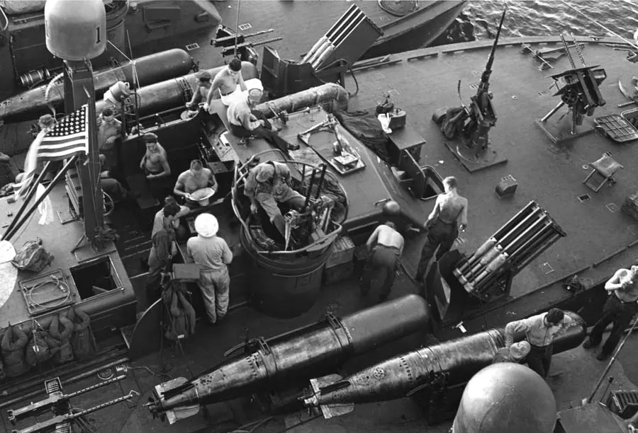
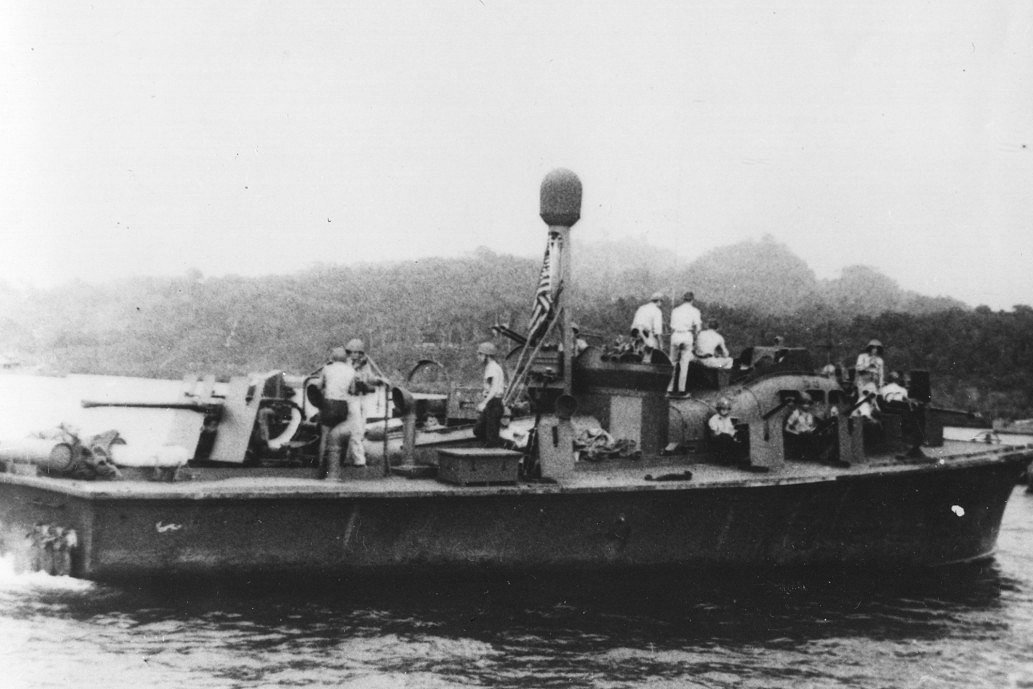
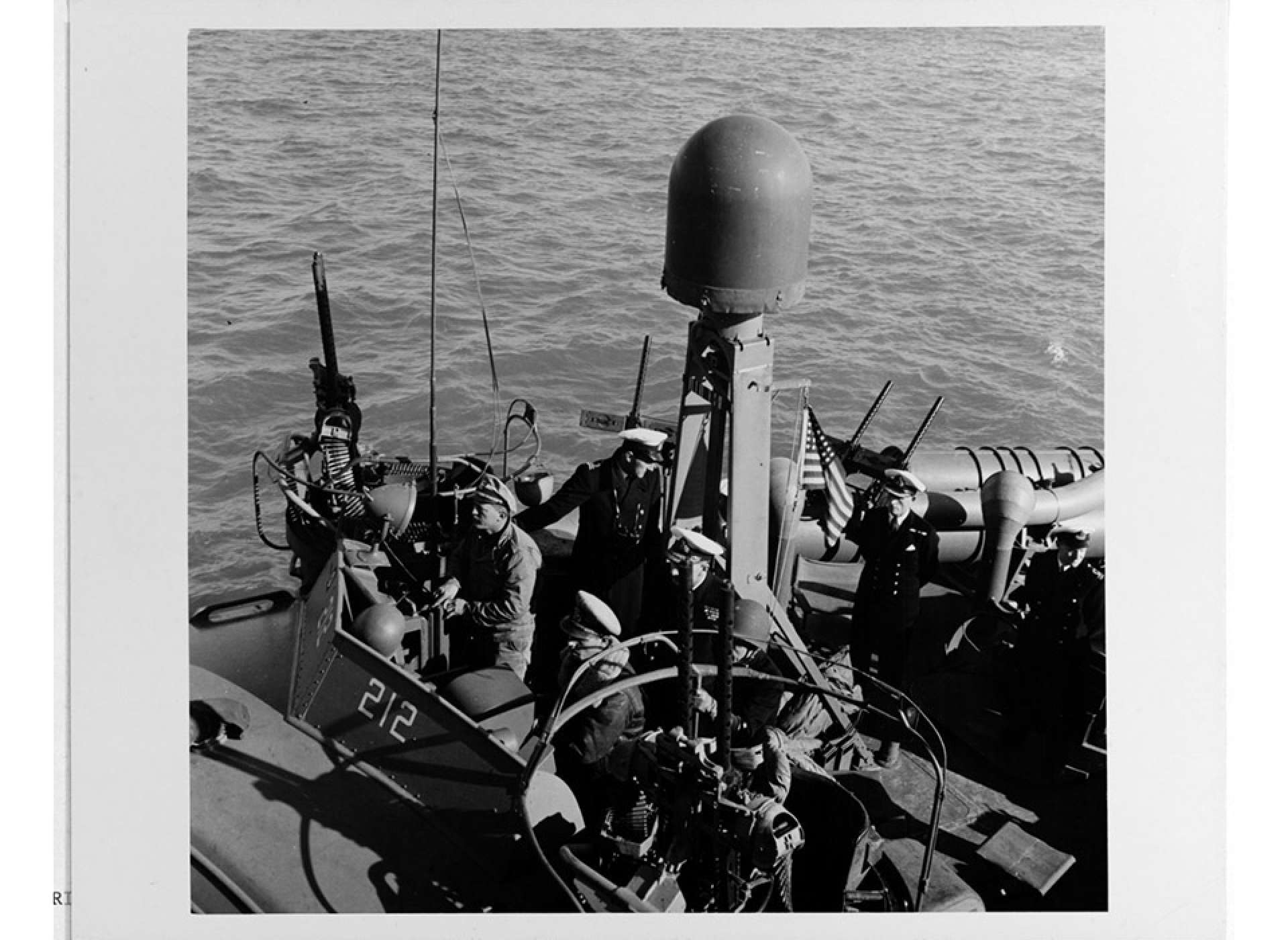
ELCO 77 foot boats were originally armed with four torpedoes in four torpedo tubes, two twin 50 caliber Browning M-2 aircraft type (air cooled) machine guns in two wooden turrets behind the cockpit one on each side of the main cabin, and two pedestal-mounted 30 caliber Lewis guns on the foredeck. The turrets were covered with plastic glass covers much as aircraft might have and had a hydraulic system to rotate the turret and aim the guns. Soon after arrival at this topical assignment, the crews of RON 3 found the plastic glazing made the turrets very hot and the humid air fogged the glazing. The hydraulics maneuvering the guns were also too slow for use in combat against aircraft. Crews soon stripped off the glass covers and the removed the slow hydraulic system and the guns were then rotated by the gunner who pushed his seat around as needed using his legs and back for power to rotate the guns. The "turrets" were thus open to the weather and sea spray and soon had canvas water shields fitted. These change occured immediately after the war broke out, probably on December 8, 1941. Around the same time, the crews re-painted the boats green as better cover from air attack.
Subsequent ELCO 77 boats were manufactured and deployed without the turret covers and hydraulics as the feedback from crews at the front was rapidly incorporated into design changes in later boats. This continual communication and improvement in the PT boats continued throughout the war, and each new series of boats incorporated improvements over the prior. This is something for the model builder to remember, as plans for PT Boats based on the Navy contract or builders' plans may not reflect modifications in armament made at the time the boats were commissioned. See section on pt armament for more information. Also, many boats were extensively modified in the field by the crews. See notes on Kennedy's second command the PT 59 for one example.
PT Boats, in most areas including the Pacific Islands and the Mediterranean, operated primarily at night. This was both because their targets operated at night and because night operation improved the odds of survival of the PTs, particularly when operating against superior forces or where enemy aircraft were a danger. In practice, this meant that the boats operated out of forward bases where the crews could refuel and re-arm the boats during the day under cover, and the crews could eat and sleep between the night-time missions. Many of these operating bases were small, with primative conditions for repair and refitting of boats and crew. They were often located in small estuaries where they could take advantage of heavy tree cover to hide the operation. There were some larger bases to provide better repair and supply capacity. The larger bases usually had two or more squadrons assigned to them. Perhaps the best known is the Rendova PT base in the Solomon Islands established in 1943. Motor Torpedo Boat Squadron 9 (RON 9) and Motor Torpedo Boat Squadron 10 (RON 10) were based there. These squadrons included PT Boats PT-103, PT-104, PT-105, PT-107, PT-109, PT-117, PT-154, PT-155, PT-156, PT-157, PT-158, PT-159, PT-160, PT-161, PT-162 and PT-164 and PT-174. John Kennedy in PT 109 departed from Rendova on the final mission of that PT Boat.
Because the boats tended to be "yarded up" during the day, they were particularly vulnerable to air attack, and at some bases the crews resorted to anchoring the boats widely apart in rivers or close in along a forested coast to better hide from air attack. In the Pacific, some additional camoulflage measures the crews took included repainting the boats green, covering up the light gray standard Navy color, painting over or otherwise covering the glass in cabin windows to prevent light escape from the cabin and avoid reflections from the glass. Crews also sometimes repainted the boat's numerals, changing them from white to gray or even black. For RON 3, the crews repainted the boats early on, using a green paint available locally and cutting the paint with gasoline to reduce the gloss of the finish. This practice continued through the early months of the war and crews experimented with various paint colors and camoulflage patterns in the field, until late in the war, 1944, when boats began to come from the manufacturer with a standard camoulflage paint pattern defined by the Navy.
In the Philippines,at the outbreak of war, General Douglas MacArthur was in command of US Army forces in the Far East. He was based in the Philippines, where, as the Japanese advanced, he declared Manila an "open city", ordered US Army forces to retreat to the Bataan peninsula across Manila Bay from the city itself and relocated himself and his headquarters staff and families to the fortified island of Corrigidor at the tip of the peninsula, which protected the seaward approaches to the Bay. At that same time, the entire US Naval forces in the Philippines,under Admiral Francis Rockwell, consisted of a submarine tender ("USS Canopus"), a rescue submarine, two mine sweepers, a few gun boats, and RON 3. PT 31 and PT 33 were lost early in actions against the invading Japanese forces, PT 33 in December, 1941, when it ran aground during a night mission and PT 31 in January 1942, when engines failed during a mission and it ran onto a reef.
Fearing that MacArthur would be killed or captured in the Japanese advance, President Roosevelt ordered that he evacuate from the Philippines. The evacuation was first planned to be by submarine, the "USS Permit", but as the Japanese advance progressed quickly, MacArthur moved the date earlier and decided go by PT Boat to the larger island of Mindanao where he could be evacuated by air rather than wait for the submarine.
Lieutenant John Bulkley,the skipper of PT 41 and commander of RON 3 commanded the the remaining four boats of RON 3 (32, 34, 35, 41) as they evacuated MacArthur, Admiral Rockwell, and top staff and families from Corrigidor and Bataan peninsula to the larger Phillipine island, Mindanao, on March 11, 1942. From Mindanao the evacuated personnel flew via B-17 to Australia. The difficult 600 mile trip was made through heavy seas, avoiding Japanese surface ships and aircraft. MacArthur and family went aboard PT 41 and Rockwell and staff went on PT 34, Lieutenant Robert B. Kelly, skipper. PT 32 became separated from the others and disabled during the trip and was scuttled and sunk by the US Submarine, "USS Permit", which was heading to Corrigidor. Permit took the crew of PT 32 back to Corregidor.
The PT officers and crew who made it to Mindanao were later evacuated by air or left on Mindanao and surrendered there. To make room for the evacuees, about 30 PT crewmen from the four boats had been left behind and joined army personnel on Bataan.
None of the boats of RON 3 survived the war. PT 34 was destroyed in an air attack by a Japanese float plane near the island of Cebu in April of 1942. PT 35 was destroyed to avoid capture on Cebu a few days later. The last remaining boat, PT 41, ended her days as an Army gun boat on a lake in Lanao when gasoline and torpedoes were gone where she was destroyed to prevent capture by Japanese forces later that same month.
The initial experiences of RON 3 held many lessons for subsequent operations of PT Boats. The three engines, Packard Marine 12 cylinder liquid cooled engines, ran on 100 octane aviation gasoline and generated 1,200 HP under optimal conditions. Improvements in the engines during the war increased HP to 1,500, then to 1,850, but increases in HP did not necessarily result in improved performance, as added armament increased the weight of the boats offsetting any improved speed. These engines were marine versions of the Packard aircraft engines. The marine versions also had superchargers, dual magnetos, and two spark plugs per cylinder. All this meant that the engines were complex and needed skilled and constant maintenance and ready access to spare parts. And they were incredibly thirsty. Using all three engines, a PT at cruising speed of about 25 knots, burned around 200 gallons per hour. At top speed, it burned 500 gallons per hour. A PT boat had a fuel capacity of 3,000 gallons. In addition, fuel for the PT boats at forward bases was often handled in small 55 gallon drums. Handling the fuel this way and the several transfers involved to get the fuel into the boat resulted in much of the fuel being contaminated by water and debris. Later in the war, the Navy developed PT boat tenders, which could transfer fuel directly to the boats avoiding much of the contamination. But that was later. PT boat crews were on the lookout for seaplane tenders in the meantime and would beg aviation gasoline from them when they could.
All the above is to say that PT Boats were generally not as fast as popular mythology and wartime propaganda would have us believe. Many missions were run at slower speeds, on one or two engines, to save fuel. Many missions were aborted by engine failure due to bad fuel or lack of spare parts. An old doggerel attributed to a PT Engineman runs:
"Some PT's will do sixty
And some will do fifty-nine
If I can get mine to run at all
I think I'm doing fine"
There were two series of 77 foot ELCO PT Boats.
Early ELCO 77 foot PT boats (PT 20 class; PT 20 - 44) had four Mark 8 torpedoes, two twin mounted 50 caliber Browing air cooled machine guns in turrets aft of the cockpit, and two Lewis guns mounted forward of the pilot house on pedestals. These boats were lightly built, intended for use in coastal waters, but were soon being used in open waters where the pounding of heavy seas caused damage to the structure of the boat, specifically cracking of the deck frames in the mid portion of the vessel.
Late ELCO 77 foot boats (PT 45-68) added wooden deck stiffening timbers on the top of the deck alongside the cabin and beside the engine room hatch and to reduce flexing of the hull when operating in heavy seas.
The first 77 foot boats had a cabin which contained the pilot house in the front, an open cockpit just behind with a door into the pilot house, then an abrupt slight decrease in height behind the cockpit as the cabin continued aft over the engine room. The after portion was fastened to the forward part with removable connections as that part of the cabin over the engine room needed to be removed if swapping an engine. There were steps on the side of the cabin to climb up into the cockpit from either side. The second series of boats eliminated the abrupt change in height of the cabin aft of the cockpit and faired the forward part of the cabin smoothly into the after part. It was still necessary to climb up and over the side of the cabin to enter the cockpit, something changed with the 80 ELCO design. And never present in the Higgins.
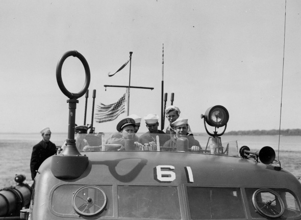
The original design of these boats assumed that they would be conned from inside the pilot house with a helmsman stationed there taking direction from an officer in the cockpit in some situations. There were duplicate controls in the cockpit, including a helm, and in the field crews soon abandoned the original plan and controlled the boat entirely from the cockpit. To reduce reflection from the glass windows in the pilot house, they were soon covered with canvas or painted over. Later the pilot house became the location used by the radar operator and radioman during missions.
Here's a picture of the front of the cabin/pilot house on PT 61, one of the second series of 77 foot ELCO boats. You can see the windows with the spinning wipers/spin windows for pilot visibility, a feature discarded on the 80 foot boats. There is also no radar.
This class eliminated the plexiglas enclosures and hydraulics for the 50 caliber machine gun turrets, which had been discarded by the crews in the South Pacific anyway. The turrets were reshaped a bit with the addition of the new rotating ring mount for the machine guns. By this time also, a 20 mm Oerlikon auto cannon had been added to the after deck. And in the field, crews added additional 50 caliber machine guns.
As the "late" 77 foot ELCO boats came on line, they were assigned largely to the Pacific, joining existing squadrons there as replacements for boats lost as well as forming new squadrons. The boats in the Pacific all had modifications in weaponry as crews adapted to changing combat conditions and different targets.
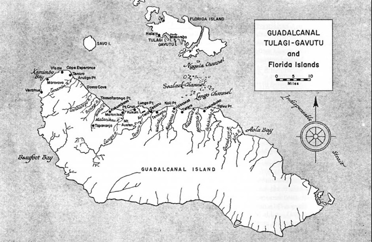
The Solomon Islands and the Guadalcanal Campaign
The "Guadalcanal Campaign" began in August 1942 and lasted six months, until February 1943. It was a combination of land and sea operations in the Solomon Islands to capture and hold an important air field being build by the Japanese on the island of Guadalcanal. The airfield was within striking distance of many Allied held islands in that part of the Pacific, and potentially within flying distance of Australia. Its construction was begun by the Japanese in July of 1942 and was an immediate threat to Allied operations in the nearby islands which were part of the outer defensive perimeter for Australia and New Zealand.
The battle began with amphibious landings by U.S. Marines on Guadalcanal and several smaller islands nearby in August, 1942. They captured the airfield in about 36 hours but then the Japanese resistance stiffened and a long land battle for the north of the island began.
The Japanese Navy counter-attacked by striking the Naval fleet supporting the landings with devastating results for the Allies. Naval engagements continued through the rest of the campaign to the point where so many ships had been sunk that the straight between Guadalcanal and adjacent Florida Island became known as "Ironbottom Sound".
Through all the campaign the Japanese sent destroyers and barges to the islands to reinforce and resupply their troops. The nightly "Tokyo Express" was very successful at increasing troop numbers and keeping the forces supplied and was the primary target of U.S.PT boats operating in the Solomon Islands. In essence, the role of the PT boats was primarily to support and protect the forces on Guadalcanal and other islands for the six months of the campaign. The boats supported amphibious landings, transported troops among the islands, and interdicted Japanese resupply of their troops.
In the Solomon Islands in 1943, three 77-foot (23 m) PT boats, PT-59, PT-60, and PT-61, were converted into "PT gunboats" by stripping them of all original armament except the two twin .50 cal guns mounted in the turrets and adding two 40mm Bofors cannons and four to six single or twin .50 cal machine guns on pedestals along the sides where the torpedo tubes had been removed. The additional weight was probably excessive, as later boats only carried a single 40 mm Bofors on the after deck. But these gunboats were an experiment in the field by crews trying out differing gun configurations to adapt the boats to differing combat needs. By that time, with the PT boats mostly targeting supply barges, the additional firepower was needed for "barge busting" and for close in-shore support of amphibious landings. Further, there were few engagements with capital ships involving PT boats, so torpedoes, which were ineffective against the shallow draft barges anyway, became less and less useful.
In the Solomons, the PT squadrons were made up of a mix of the two variations of the 77 foot ELCO boats and soon included the new 80 foot ELCO boats. There were a lot of PT bases in the Solomons on many islands there. And the bases were relocated as the situation needed.
Bases in the Solomons included locations at Espiritu Santo - New Hebrides, Tulagi, Rendova, Lever Harbor, New Georgia (Advanced Base), Vella Lavella (Advanced Base), Treasury Island, Cape Torokina - Bougainville, Green Island, Homestead Lagoon - Emirau.
Although PT boats did not often encounter large capital ships and the number of large ships sunk by PT boats is small, they were effective at interdicting barges moving troops and supplies to the islands, in transporting Marines to and from islands, and at close shore support for ground troops.
As the war progressed, the PT boats of the Solomon Island campaigns moved on. Most PT boats from the Solomon Campaign that survived the war ended their service when scuttled and burned in 1945 at Samar, one of the islands of the Philippines.
The first 77 foot ELCO model I built was of the PT 34. I made it from plans by Al Ross, JR, of Coastal Forces and Bluejacket Shipcrafters. He has created a wonderful series of plans of many PT boats and his plans are the basis of all my models of PT boats to date. His father was a crewman/gunner on the PT 34 and was wounded during an air attack on the boat was left behind while recovering when the boat left Corregidor during the Macarthur evacuation. Ross was captured, and finished the war as a POW. The PT 34 transported Rear Admiral Francis Rockwell and Brigidier General Richard Marshall during the MacArthur evacuation.
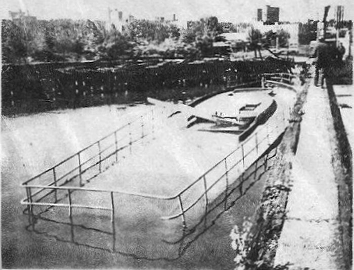
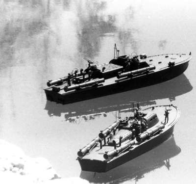
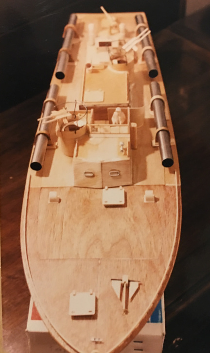
I built the first model of the 34 in Saudi Arabia in 1:32 scale. Here is a picture of it floating in a pond in the diplomatic quarter in Riyadh along side a companion in the background, a model of the PT 109, my second PT model from Al Ross plans:
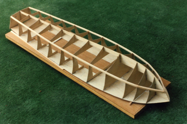
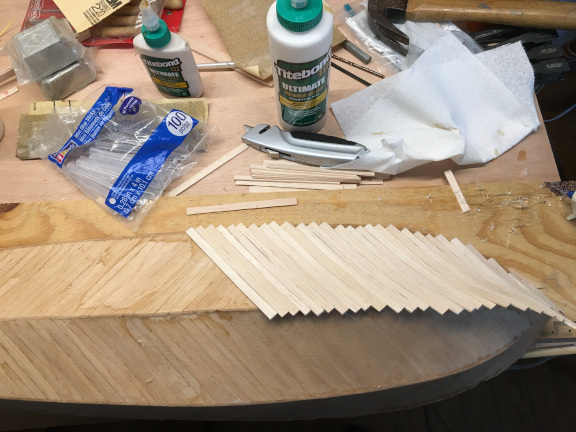
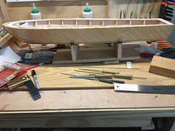
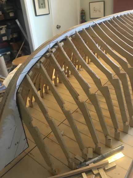
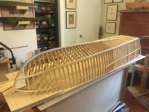
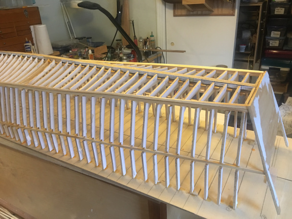
The model was basically a plank-on-bulkhead technique, using the Coastal Forces (Al Ross) plan as a template to make bulkheads at each of the stations on the hull plan. I then designed a keel using the profile plan, notched at the stations for the bulkheads. Keel and bulkheads were cut from 1/32 inch birch plywood and the hull planked with two layers of 1/32 inch balsa planks, each about 1/4 inch wide, placed diagonally much as on the original. Here are some photos of the hull in progress.
A picture of the bulkheads set up on the keel, then the chine timbers added.
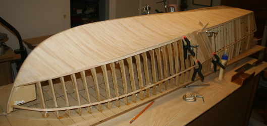
I made the construction extremely light in weight as I wanted a model that would be fast. When I glued the bulkheads to the plywood base for the deck, I shimmed the forward part of the deck to recreate the characteristic downward slope of the forward part of the deck at the bow. The planking was glued with cyanoacrylate glue. Once the hull was planked, I planked the deck with more balsa and installed the running gear. I used a fast running 540 motor with a simple mechanical speed controller and a 7.4 volt battery. It powered a very oversize single screw plastic propellor and the model went like a rocket.
The photos below show the planking - finishing up the second layer. And the deck in place with access for the running gear and rudder.
I painted the model a dark green and used a few 1:35 scale military figures to make some crew. I carved up and reassembled the figures to suit.
Here are some photos of the finished model with crew. The last is an overview of the painted model before adding figures and other detail.
Upon return to the U.S. and the farm, I set up a model workshop in a part of the barn originally finished off as an office for the business and the yarn shop. I used it to make some stick-and-paper rubber-band powered model air planes and multiple "whirley gigs", and other projects with the kids. In 1987-88, I built a model of the PT 59 in 1:16 scale using plans from Al Ross and the plank on bulkhead method used for the smaller PT models, just with larger dimension material - 1/16 inch birch plywood for the bulkheads with additional frames/bulkheads interpolated between the station lines. PT 59 was a late 77 foot ELCO converted to a gun boat in 1943. Information on the PT 59 is here.
This model was also built as an RC model. I used a single motor driving a home made gearbox that ran the three propellers. The props I used were to scale and the model did not run as fast as I wanted, as the single motor was too small and the props were too small also. In addition, as I increased the power to the motor, the props rotated fast enough to produce enough cavitation and turbulence that the scale size rudders became ineffectual. This was a problem I had had with the original PT 34 model, which had a large prop with more pitch than the original so it created even more turbulence than the three smaller props on the 59. I had solved the problem with the PT 34 model by installing a much larger rudder that was placed deeper than the propeller, below the turbulence. I did not want to use that approach with the model of PT 59, so I left the scale props and rudders and kept it as a static scale model.
For the guns, I used commercially available cast metal versions of the machine guns and of the two Bofors 40mm cannon. The model ended up looking pretty good and was eventually donated to the PT Boat Museum in Fall River, Massachusetts.
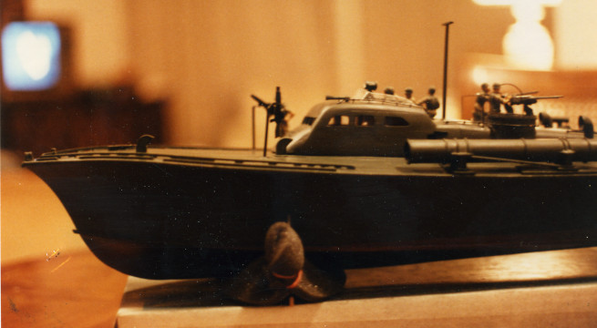
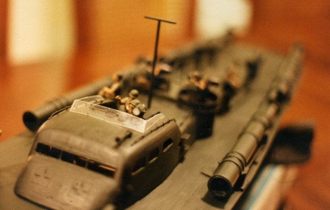
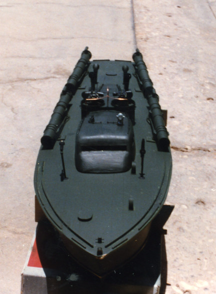
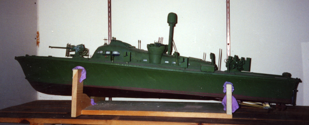
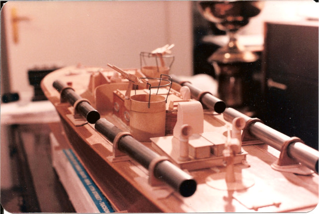
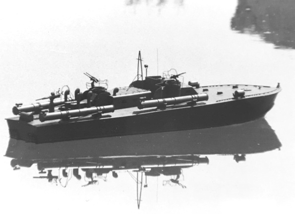
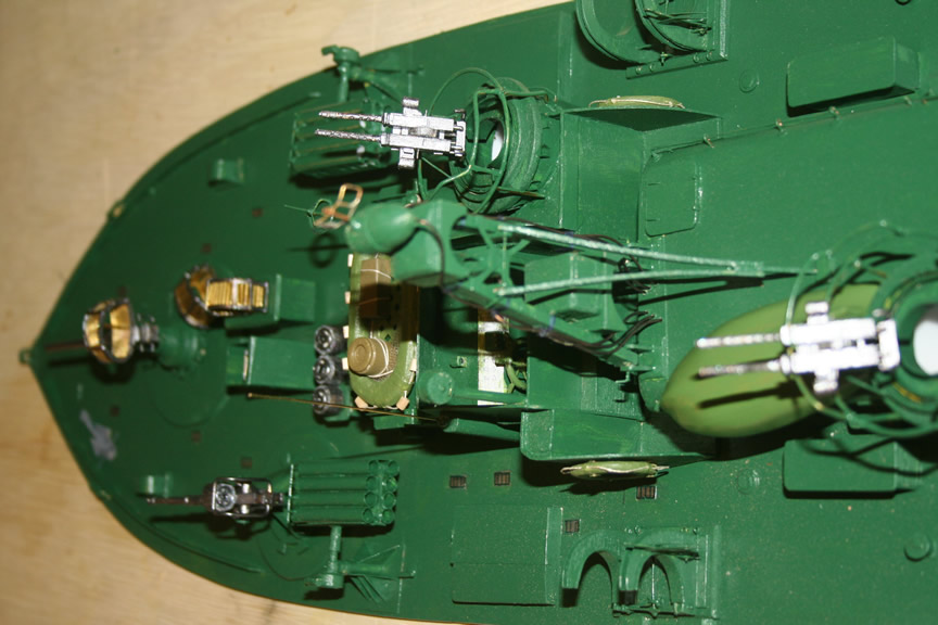
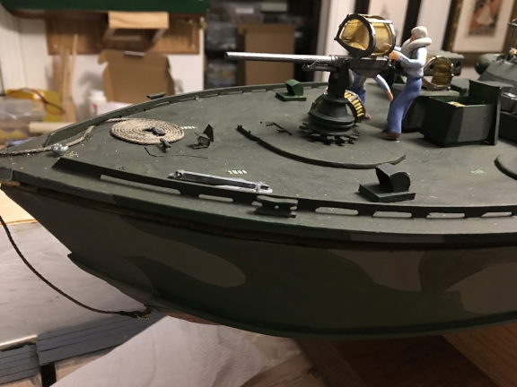
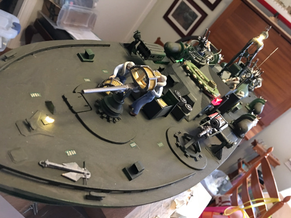
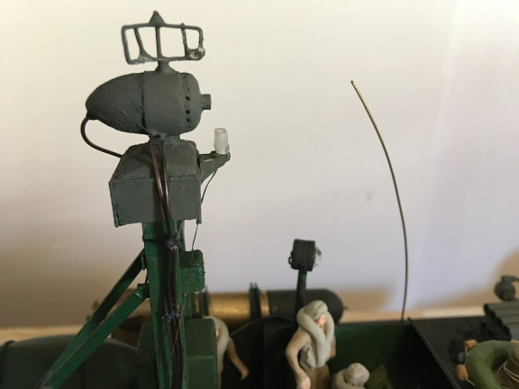
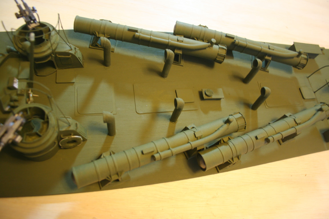
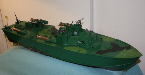
I don't have any pictures of the model under construction or any detail photos of the completed model. Here are a few pictures of the model in the water of our irrigation pond at the farm and on its cradle on the shelf in the workshop. In the first photo, you can see some of the distinguishing features of the late 77 foot boats, including the smoother transition from the pilot house to the engine room cabin and the deck stiffening timbers along the cabin and the engine room and a second timber over the rear of the deck, along side the Bofors there. The boat had radar, folded down in the first photo, and the turrets had higher sides to lessen the water splashing into them when underway.
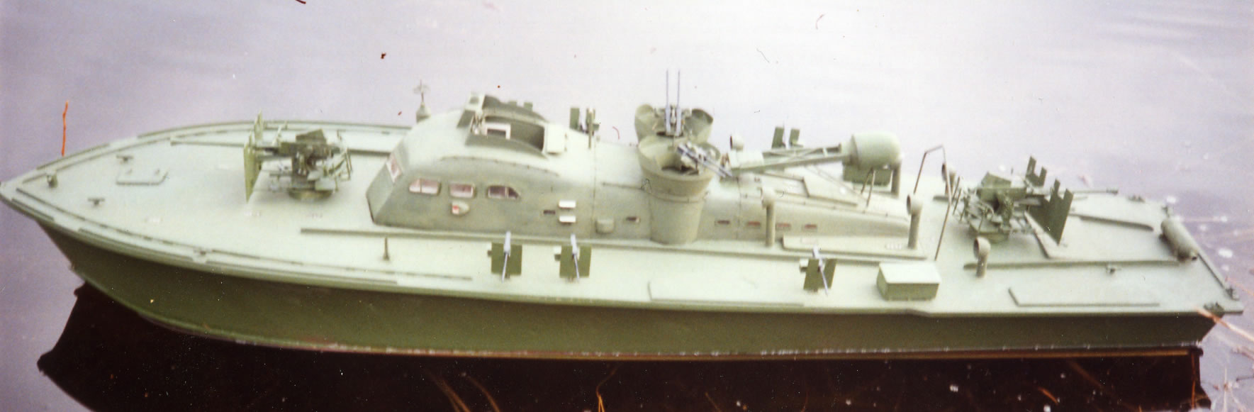
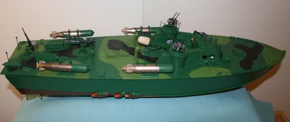
Here's a picture of the port side of the boat. The radar mast is set up in operating position. The dome of these early radars was of a white plastic and was therefore very visible to enemy aircraft, so it was covered with an olive drab canvas cover when not in use and stowed.
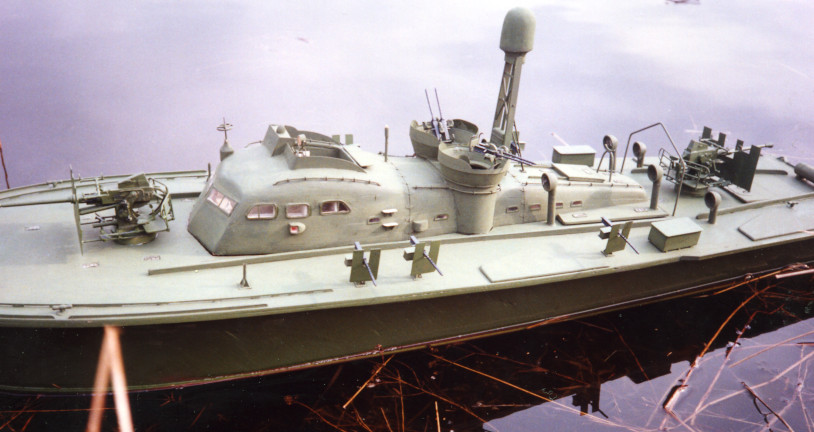
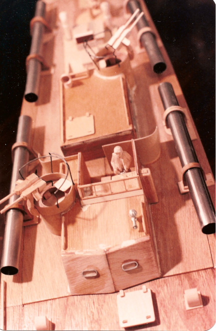
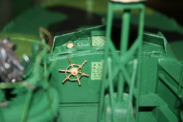
Here's another shot of the model from a different angle. You can see that the door to the pilot house from the cockpit is open. I built the model with a detailed interior of the pilot house, including the radar operator's console and gear. The inside of the pilot house I painted white, the original color, although in the field, the crews likely repainted the interior. And certainly would have painted over or covered the pilot house windows. I left them unpainted to show off the interior. And the "spin windows" on the forward glass.
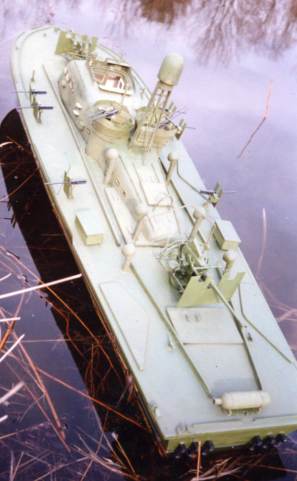
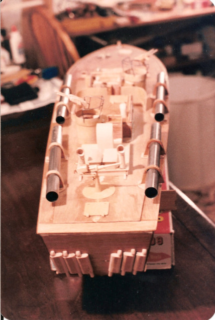
And a final picture of the 59 on its cradle. You can see the size of the props and rudders in this picture. Even though its performance as RC model was disappointing, it made a fine scale model.
In 2015 after we returned to New Orleans, I started a series of PT boat models, all in 1:32 scale. This effort was stimulated by the history of Higgins Industries and our proximity to Bayou St. John. Higgins built PT hulls at a plant near our home, at the site of an industrial school, near where today, Delgado Community College still stands. When near completion, the hulls were loaded by crane on railroad flatcars and transferred to a second manufacturing location where the hulls were fitted out. The final stages in PT boat constuction took place in the upper part of that Bayou, near where it enters Lake Pontchartrain. And the PT boat "sea trials" at the time of acceptance by the Navy were on the Lake.
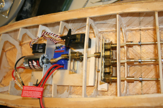
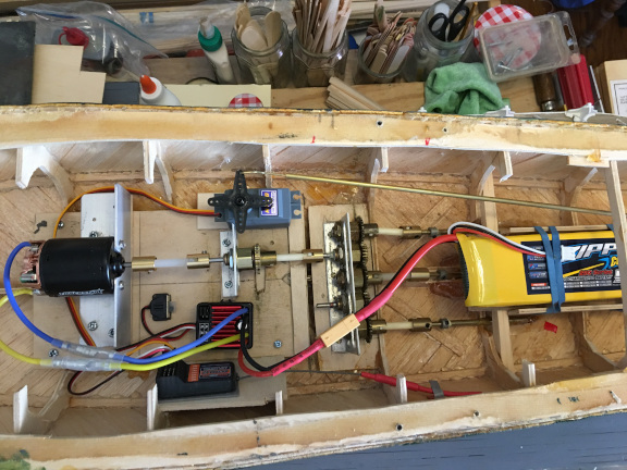
For the series, I built a hull for an ELCO 77' boat, one for an ELCO 80' boat, and one for a Higgins 78' boat. All were radio-controlled and electric powered. The drive train was a module using one motor and a gear box to drive all three props plus the RC reciever and a servo for the rudder. The gear boxes were made from standard Dumas gears. The drive module fit all three hulls and could be switched along with the receiver from one hull to another reducing cost.
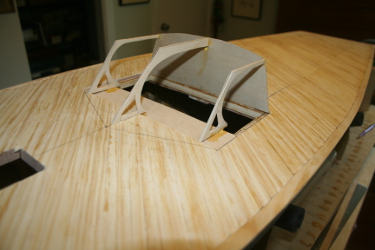
I then built two decks for each hull: an example of an early version of each type and a late version. For the early ELCO 77 boat, I chose to model the 34 again:
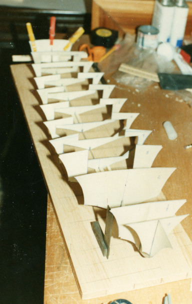
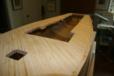
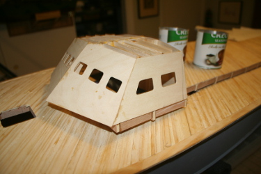
Here's a picture of the two decks for the 77 foot ELCO hull, PT 34 at the top and PT 59 below.
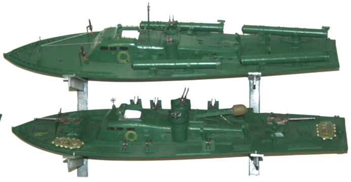
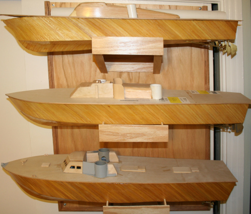
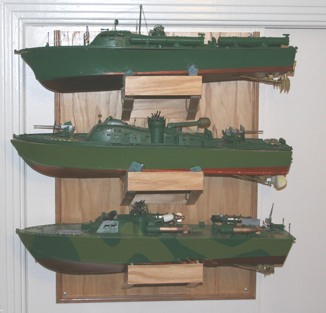
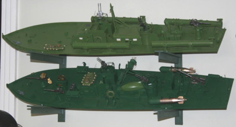
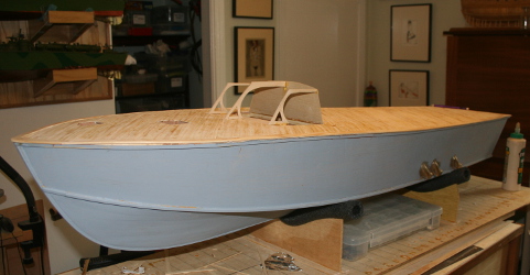
Photos of the three hulls, the first with the completed hulls and the one of the decks for each with the cabin and turrets started, and the second of the three hulls with one of the completed decks. The picture on the left shows the 77 foot ELCO on top, the 80 foot ELCO in the middle and the Higgins on the bottom. The picture on the right shows PT 109 (early ELCO) 80) on top, PT 59 (late ELCO 77) on the bottom and a late Higgins with roll off torpedoes, radar, and two 20 mm cannon. Note that each hull has different shaped rudders 3 on the ELCO boats, two on Higgins, although all use the same scale props. Each deck was duplicated, incorporating differences between early and late as needed. There are more pictures of completed decks in the general information section.
The swappable drive train module fitted in the 77 foot hull.
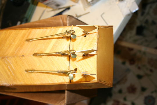
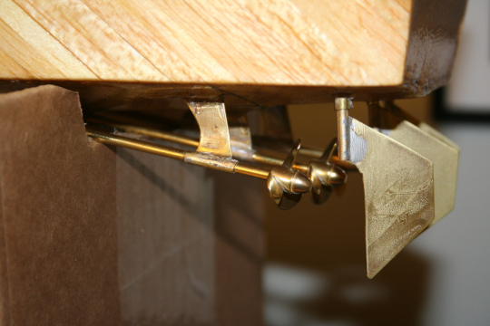
Photos of the props and rudders for the 77 foot ELCO hull. Props from Dumas rudders and shaft struts fabricated from brass.
Second model of PT 59 in 1:32 scale
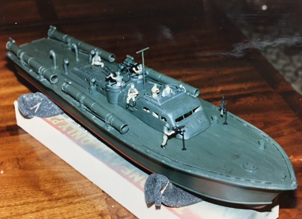
For the late ELCO 77, I modeled the PT 59, using the Al Ross plans I still had on hand. Here's a photo of the actual PT 59 before and after modification. There is more information on PT 59, her association with John Kennedy, her long and varied career, and her ignominious end here.
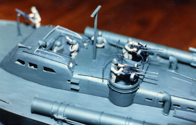
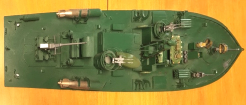
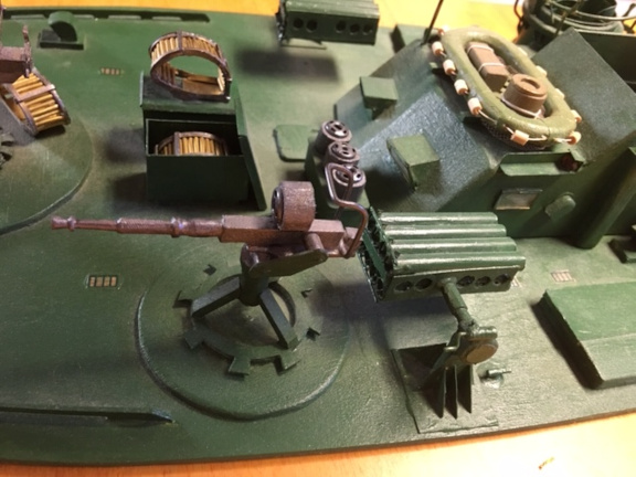
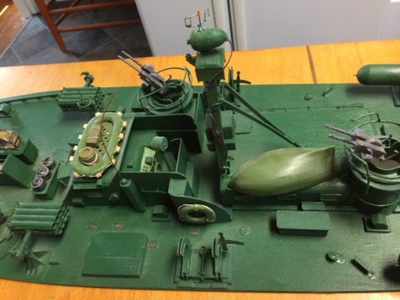
PT 59 was one of three late ELCO 77 foot boats (PT 59, PT 60, PT 61) field-modified in the Solomon Islands into full out gunboats. The crews removed the four torpedo tubes and installed two 40mm Bofors cannons, one on the foredeck and one aft, and augmented the machine guns in the turrets with additional pedestal mounted 50 caliber machine guns mounted along the sides of the boat. Accounts and pictures differ as to whether the additional machine guns were twin mounts or single mounts and also as to how many were installed. Likely it varied with experimentation. This adaptation was done because by that time in the war (1943) there were few large Japanese vessels operating in the island chains and the Japanese were using armored barges to supply and reinforce their troops as they threatened to retake Guadalcanal. Witn no capital ship targets worthy of a torpedo and shallow draft barges that were unsuitable targets for the deep running torpedoes, the armor of the barges, resistant to machine gun fire and the 20 mm cannons that were standard equipment on PT boats needed to be overcome. The Japanese piloting the barges had learned to keep the heavily armored landing ramp pointed at attacking PT boats to resist the gun fire. PT boat crews needed to up the ante by installing the larger guns and more machine guns for "barge busting" and close inshore support of Marine troops. Experiments such as these led to the later gun configuration of PTs as built, such as that of the PT 592 class of ELCO 80 boats and the later Higgins boats. Note also that this boat had radar. That was a new development and an example of how PT boats were constantly updated and modified during the war.
There's more information on the PT 59 here.
Early ELCO 80 foot PT Boats: PT 109 (Class 103)
Some photos of the 80 foot ELCO boats. These are clearly new designs and incorporate improvements such as simplified cabin design, better access to engine room when replacing engines, and overall, a larger more rugged hull better suited to be a gun platform. These are photos of the first class of the 80 foot boats, the "PT 103 class" (PT 103 - PT 196), which initially came armed with the addition of a 20 mm Oerlikon auto cannon on the after deck. In the field, crews soon modified these boats with additional guns. See section on PT armament for more information and illustrations.
Models of early 80 foot ELCO PT Boats PT 109
There are actually three models of the PT 109. The first one was from the Dumas kit, which is about 1:30 scale and lacks detail. My friend Howard challenged me to a "build off" of the Dumas model. It was when I looked for additional information to detail my model that I found Coastal Forces and got the Al Ross plan of the 109. I used it to add a lot of detail. I also powered the boat with a fast running motor and an oversize prop so it moved pretty well in the water of the swimming pool at our Riyadh villa. Here are some pictures of the model under construction. I used locally purchased half inch stainless steel water pipe for the torpedo tubes and carved most of the rest of the detail from guns to the helmsman from pine. When it was done I painted it Navy gray.
The first pictures of the unpainted model when nearly complete.
And here are some pictures of the first boat under construction. You can see how crude the detailing was. It was only after getting the good plans that I could build a better model, a second, "new and improved" PT 109 - below.
The second PT 109 model was built shortly after the Dumas kit was completed. I used the same building technique as I had used for the PT 34 and the Al Ross plans for detailing the boat. There are two pictures of the completed boat in the pond at the Diplomatic Quarter in Riyadh. You can appreciate the finer detail. I even got the two depth charges on the forward deck, although I omitted the scrounged 37mm Army anti tank cannon she carried on her last mission. Again, machine guns adapted from 1:35 plastic military miniatures and the 20mm fabricated.
In New Orleans, when building the 1:32 scale series of PT boats, for the early 80 foot ELCO deck, I built another PT 109 from the Al Ross plans on hand. It could be any of the PT 103 class as built.
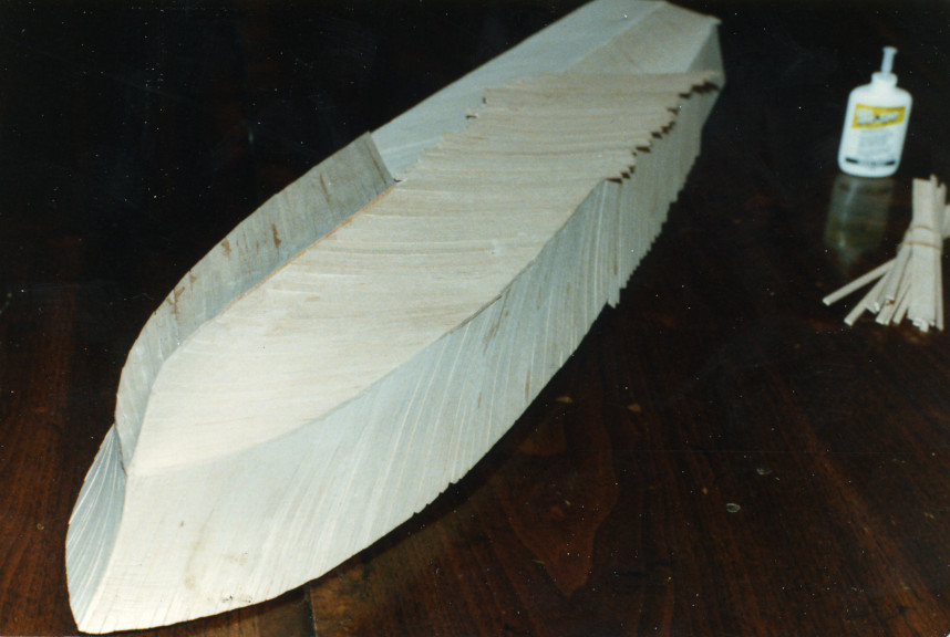
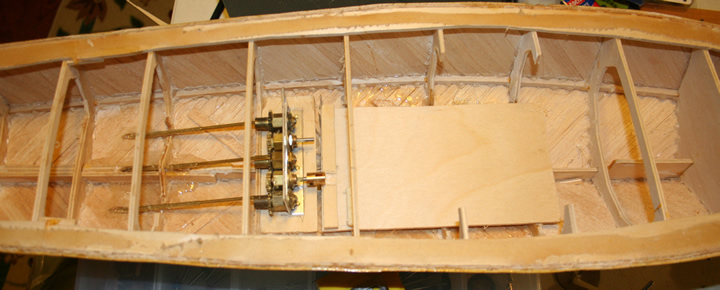
I used much the same construction technique as I used for the boats made in Riyadh, except that I used hot melt glue instead of cyanoacrylate for the hull assembly. Bulkheads were laid out from station sections and then modified by cutting away space for the RC components to be added. In addition, since the hulls were to have two decks each, I made the hull with a second deck cut away almost entirely in the center, but about half an inch wide along the gunwales. I could then make up the hull including any reverse shear in the 77 foot boat hull and the swappable hull, constructed on a base of 1/32 inch birch plywood, simply fastened down to the lower hull with small screws. The first photo shows the second layer of balsa planking going on over the first, and the second photo shows the hull after the planking is complete.
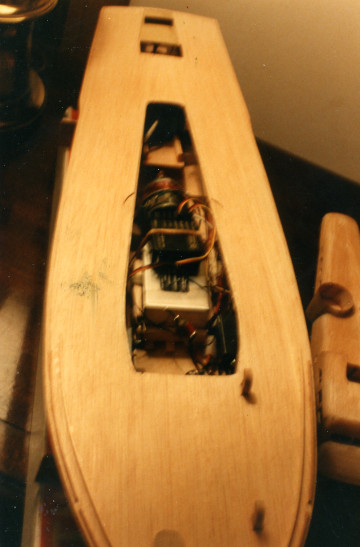
A photo of the 80 foot ELCO hull showing the gearbox and propshafts installed. The drive module from the 77 foot hull fit into the mounting in front of the gearbox and is connected to it with a dog-bone nylon connector, the same ones used to connect the gearbox to the shafts.
Two years later, I sold the 80 foot ELCO hull with a deck for the later version of the ELCO boat as described here and I was left with the early ELCO 80 deck and no hull. So I built another 80 foot hull, but this time I used three separate motors, eliminating the gearbox and greatly improving the performance of the model when in the Bayou.
Here's a shot of the second hull with the three motor mounts in place. The motors were direct drive to the prop shafts.
A couple of shots of the deck of the early ELCO 80 model. I omitted the depth charges on this one, so it could be any of the first few boats of the PT 103 class.
And finally, a photo of the early 80 footer in the water, in Bayou St. John.
Late Eighty Foot ELCO PT Boats: PT 596 and 600
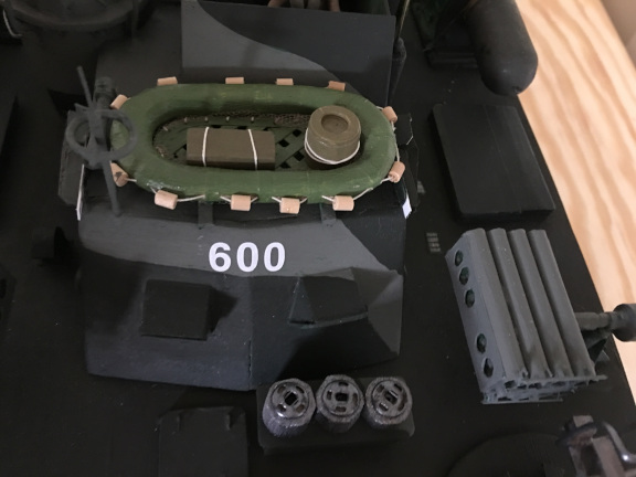
Here are the two ELCO 80 decks I made for my series. The PT 103 class above, with no radar, four torpedo tubes, and a single 20 mm cannon, and the PT 596 with two roll-off torpedoes, a 40 mm Bofors, a 37 mm auto cannon, a 20 mm auto cannon, 5 inch rocket launchers as well as the two twin machine gun turrets. It also has the third generation radar as well as additional radio equipment.
As WW2 continued and PT boats evolved the ELCO 80 foot boat basic design did not change much, but the armament changed drastically. Elimation of the torpedo tubes increased available deck space and decreased weight allowing addition of more cannon. Also, the earlier weight restriction due to the capacity of shipboard cranes were eased and the boats actually became heavier. Late ELCO boats displaced over 56 tons and weighed over 60 tons loaded. The crew increased from 11 (3 officers, 8 crew) to 17 (3 officers, 14 crew), as additional men were needed to man the additional guns.
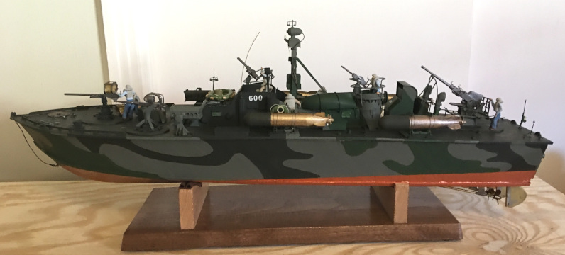
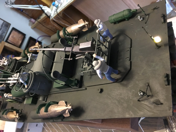
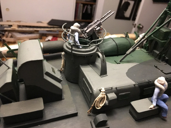
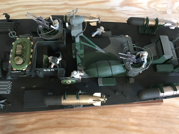
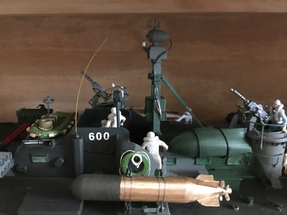
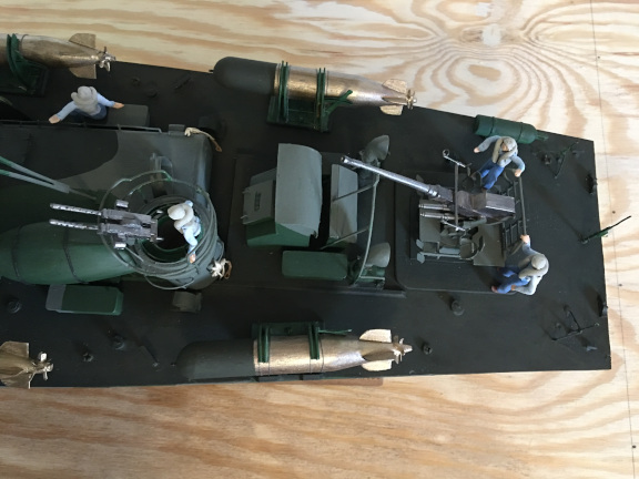
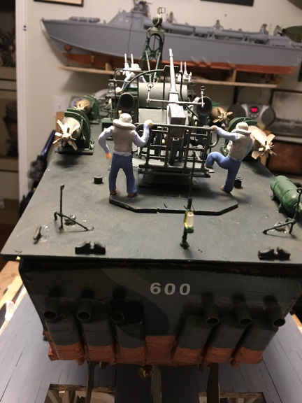
Here are some photos of the PT 596 model, an ELCO 80 foot PT Boat of 1944 (class 226-613). By this time the boats at the time of commissioning had much heavier armament, mounting roll-off torpedoes, a 40mm Bofors cannon, a 37mm auto cannon, a 20mm Oerlikon auto cannon, and two 5 inch rocket launchers in addition to the original twin 50 caliber Browning machine guns in two turrets. Boats also sometimes carried depth charges and mortars depending on the mission. By this time in the war, they were more gunboats than torpedo boats and sometimes operated without torpedoes. Individual crews and squadrons were also permitted to experiment with other versions of armament. Results of field experimentationwere fed back to the designers and manufacturers of the vessels to incorporated recommended improvements as soon as practical.
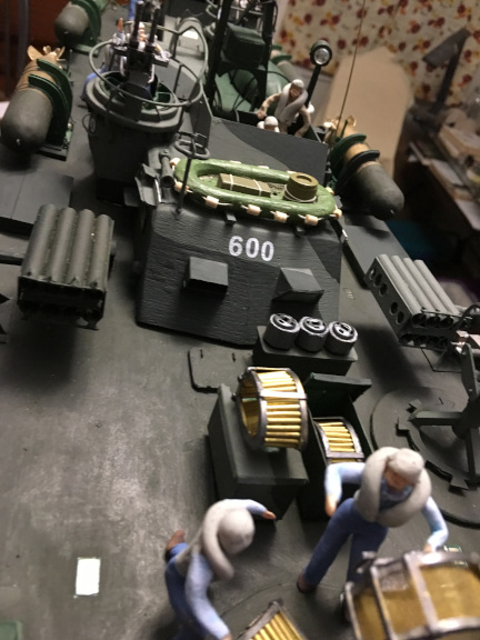
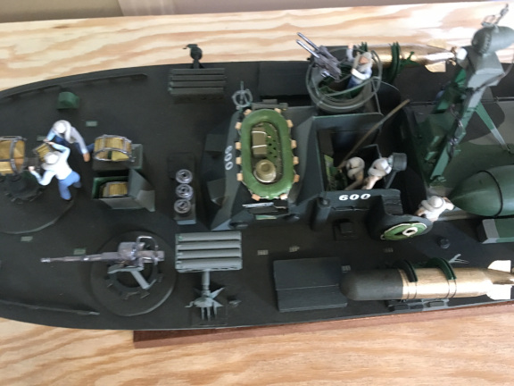
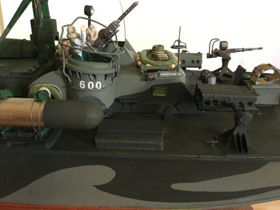
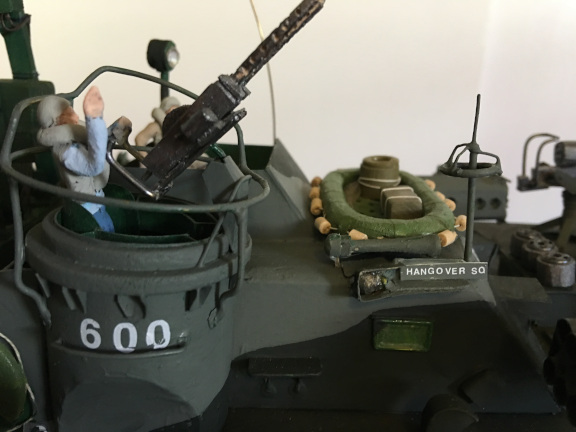
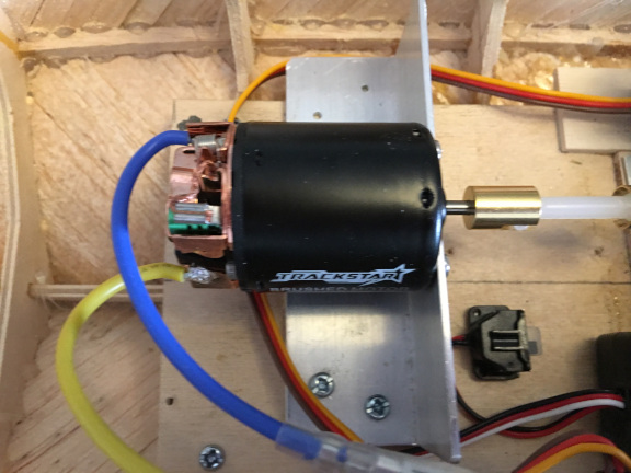
The late ELCO 80 boat I modeled for the series was from plans for the PT 597 and had the armament described above. I later modified the model for a customer, changing the number to PT 600 (nicknamed "Hangover Sq.") and modeling a crew. I also re-powered the boat, since I wanted to keep the drive module to use with the other hulls and thus needed another receiver anyway. So I powered it with a brushed 550 motor driving the props through the existing gear box. There are some pictures below of the revised drive train.
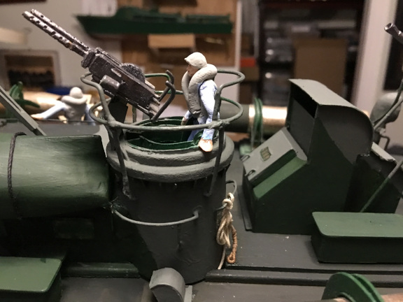
Here are some photos of the late ELCO deck after conversion to the PT 600. During the conversion, I added LED lights and repainted it in the standard camouflage pattern in use at the time the boat was commissioned. And added two more torpedoes on racks.
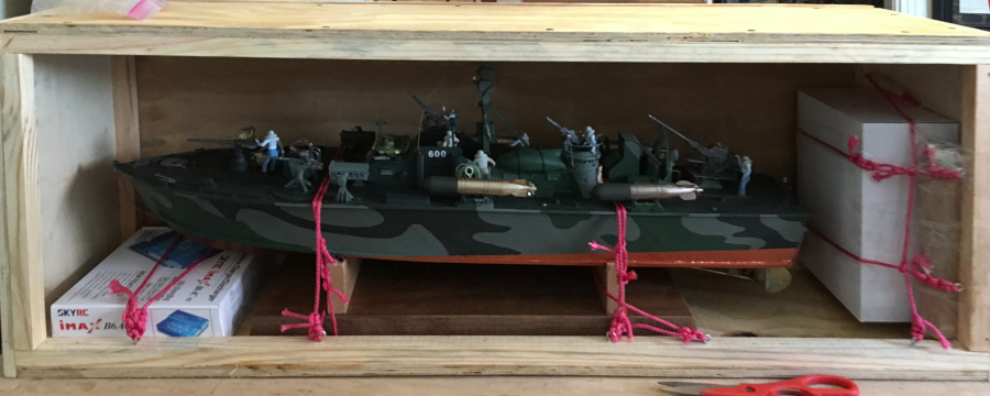
And here is the PT 600 in her crate ready to ship out.
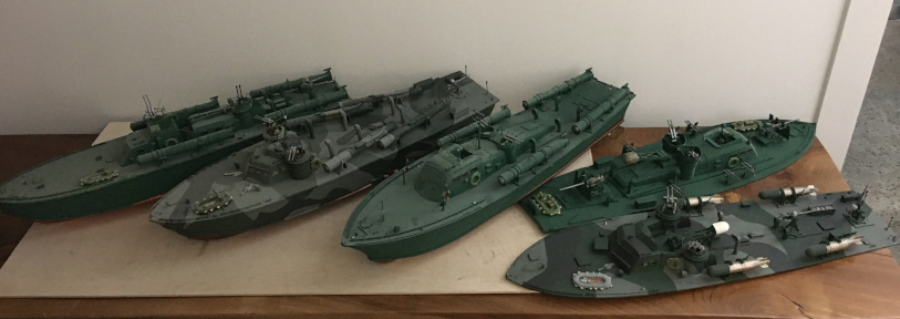
After the PT 600 was completed and shipped off, I built another ELCO 80 hull for the PT 109 deck I had "left over" as described above. And here is a final picture of the series of PTs in 1:32 scale: Three hulls and five decks.
During the time ELCO was building the new boats, other companies developed PT boat designs at their own expense. Higgins Industries, based in New Orleans, had extensive experience building working boats used in coastal waters in that area and the Gulf Coast. Higgins initially developed a 76 foot boat (PT-70) which was later changed to 78 feet length to better accomnodate the Navy requirement that the boats carry four torpedo tubes.
The Higgins PT boats were more rugged in design and the hulls underwent few changes during the war. The only change of note was that, once the torpedo tubes had been eliminated, the two turrets were moved back several feet to improve visiblity in the cockpit.
The Higgins PT Boats were designed and unitially built in New Orleans by the company owned by Andrew Jackson Higgins, Higgins Industries. Before the war, Higgins built mostly working boats for use in the shallow, swampy, waters of Louisiana. They were capable of running up on the shore without damage to the propeller, then reversing to return to deeper water. These boats led to the design of the "Higgins Boat", a series of landing craft of several types used in amphibious operations during WW2 and afterward. These were "The boats that won the war", according to Dwight Eisenhower, and were what led to the national WW2 museum being located in New Orleans.
The team at the Higgins company separately designed the "Higgins PT Boat", which had several important differences from the ELCO designed boats, both the 77 foot version and the 80 foot version. During the war, there were 23,398 Higgins designed LCVP landing craft built at the New Orleans facility and at other locations licensed by Higgins to make his design. Also, Higgins built other versions of his landing craft as well as total of 199 PT Boats at the New Orleans facilities. Higgins also shared his designs and patents without charge to other companies which wanted to make his landing craft. All he cared about was helping to win the war.
Higgins Industries had built workboats. ELCO had more experience building yachts, and its 77 foot design was more or less a direct copy of the Hubert Scott-Payne design purchased by ELCO in 1939. That boat was a 70 foot long boat designed specifically as a torpedo boat and later was given the Naval designation "PT-9" in 1941, when numbers were assigned to the various hulls under development. Scott-Payne was quite a colorful character, much as Andrew Jackson Higgins. The reader is encouraged to further read about both these men whose contributions to the development and implementation of the PT boat concept were huge.
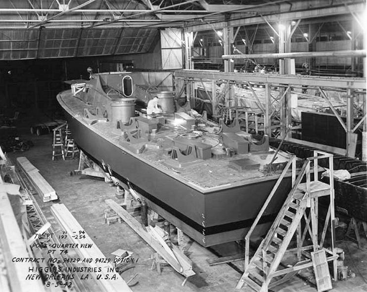
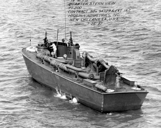
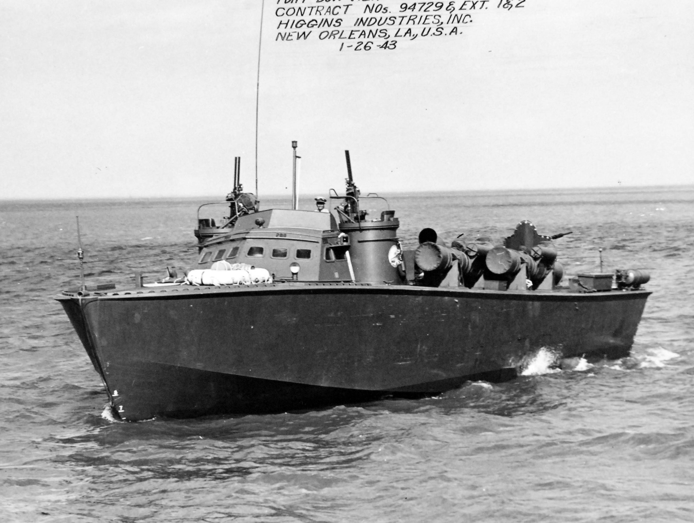
Following are some pictures of Higgins boats under construction at the New Orleans location and some of the boats on Lake Pontchartrain for their "sea trials". There are also some pictures of Higgins boats in the field. As did the ELCO boats, Higgins boats switched over to roll off torpedoes as soon as authorized by the Navy and used the added space and carrying capacity to add more weaponry. By the end of the war, Higgins boats and ELCO boats were pretty equivalent in armament and radar.
As you look over the pictures, note the different layout of the deck of the Higgins boats. There is a simple pilot house with the turrets close to it. There is simply a hatch cover over the engine room, making engine change easier. And the torpedo tubes are cleverly arranged and the torpedoes launched by compressed air. In photos of the cockpit area, you can see the openings into the turrets from the deck rather than from inside the cabin.
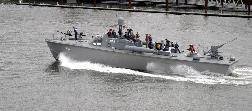
The last picture is of the PT 658, an operational surviving Higgins boat. The PT 305 was also operational after restoration at the World War 2 Museum in New Orleans and spent a year or so on Lake Pontchartrain, but has now been "retired" and will be stored inside.
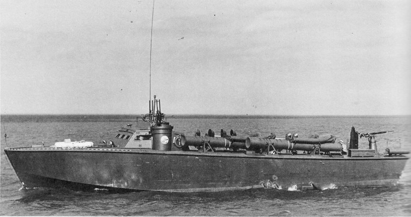
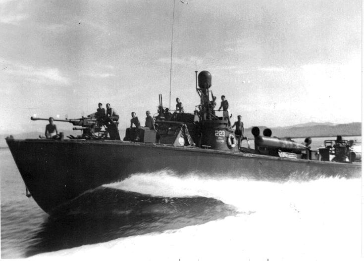
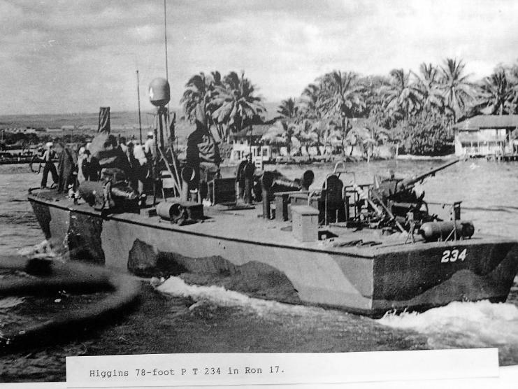
A couple of photos of the early series of Higgins boats, PT 223 and PT 234 which have been modified with roll off torpedoes, larger guns, and miscellaneous other weaponry. PT 223 was stationed in the Aleutians until 1944 when she was transferred to the Pacific. The PT 234 is in camoulflage paint and served in the Pacific. The camouflage pattern is not the "Measure 31" pattern which was the Navy standard and was likely applied by the crew. The pattern on ELCO boats did not extend over the deck but did on Higgins boats.
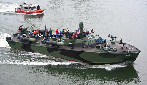
Here are photos of the PT 658. This is a later Higgins boat and has the turrets positioned several feet aft of the original position. The first shows her painted in Navy gray, the second in Measure 31 camoulflage pattern.
Models of Higgins 78 foot PT Boats
Then, when I constructed the decks, I became aware of more differences and also more impressed with the Higgins design, which clearly owed more to it ancestry of working water craft compared to the ELCO heritage of yachts and speedboats. The layout of the deck, pilot house, and cockpit was entirely practical and anticipated some of the later changes in the ELCO boats, such as the walk-in rather than climb-over-and-into cockpit. But the torpedo tube positioning and firing mechanism was really smart. The angled tubes were already in firing position. And the compressed air launching was safer and more reliable than the explosive mechanism of the ELCO boat launch.
As I learned more about the Higgins PT boats, I realized they reflected the personality of Andrew Higgins and the culture of his company, Higgins Industries. Higgins had started out as a timber and lumber company selling timber from southern forests and importing mahogany logs and operated a small fleet of ships and small boats as part of that business. In the mid 1920s, the company moved more into constructing small boats at their ship repair site on the Industrial Canal in New Orleans, near Lake Pontchartrain. Gradually the small boat design and construction part of the business over took and replaced the lumber business. Higgins concentrated on making shallow draft working boats and worked with the Army Corps of Engineers in designing boats for their use. The shallow draft boats proved their merit during the floods of 1927. Higgins continued to improve the design and performance of the small boats, even setting a new speed record for the journey from New Orleans to St. Louis, beating the record held by the Robert E. Lee in the famous "race" with the Natchez in 1870. As part of the continued development of his boats, Higgins built boats that could pass over floating logs and sandbars without damage to hull or propellers. Eventually, Higgins had boats that could run up on a shore unload and then back off the shore into deeper water without damage. The basis for the later landing craft built for the U.S.Military, the LCVP (Landing Craft Vehicles Personnel).
Higgins Industries expanded during WW2 from a single plant with less than 100 workers to a company with seven plants employing over 20,000 workers. The PT boat construction was done at two locations. The first was at a manufacturing facility near City Park, adjacent to the location today of Delgado Community College, actually the location of today's Administration building there. Once the hulls were mostly completed, they were loaded onto railroad flatcars and taken by rail on a route through City Park to the second location, on the Industrial Canal, where they were fitted out and completed. "Sea trials" were done on adjacent Lake Pontchartrain.
Higgins himself was a great supporter of the "trade school", the early Delgado College, adjacent to his City Park plant. He also had an employment policy that paid workers on the basis of their job description regardless of race or gender. If a prospective worker could pass the testing to become a welder, then that worker was paid what Higgins paid a welder. This policy generated a great deal of negative attention in New Orleans but Higgins met the criticism by stating that "We have a war to win" and he could not be bothered by Jim Crow attitudes and policies. As a result, he was a social pariah in New Orleans, and that likely contributed to the post war difficulties of the business and its ultimate failure.
Higgins was a remarkable man, who also ventured into aircraft design and construction, manufacture of prefabricated housing and commercial buildings, and probably anticipated the development of containerized shipping. He was a hard-driven and hard-driving man and in 1952, Higgins died of complications of a bleeding gastric ulcer.
The book "Andrew Jackson Higgins and the Boats that Won World War II" by Jerry Strahan is well worth reading if interested in the life of an remarkable American.
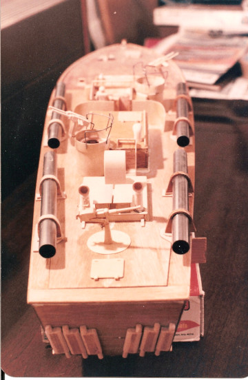
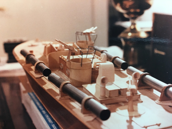
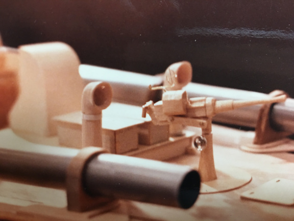
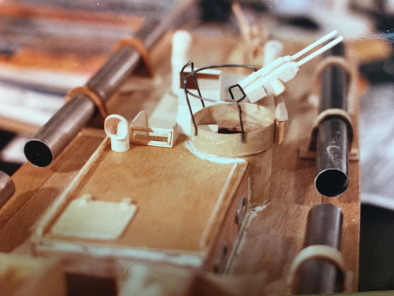
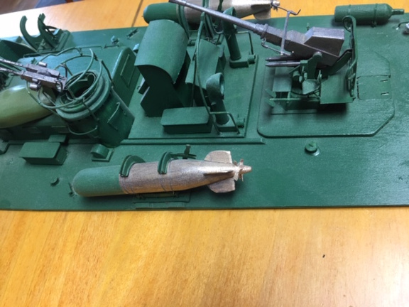
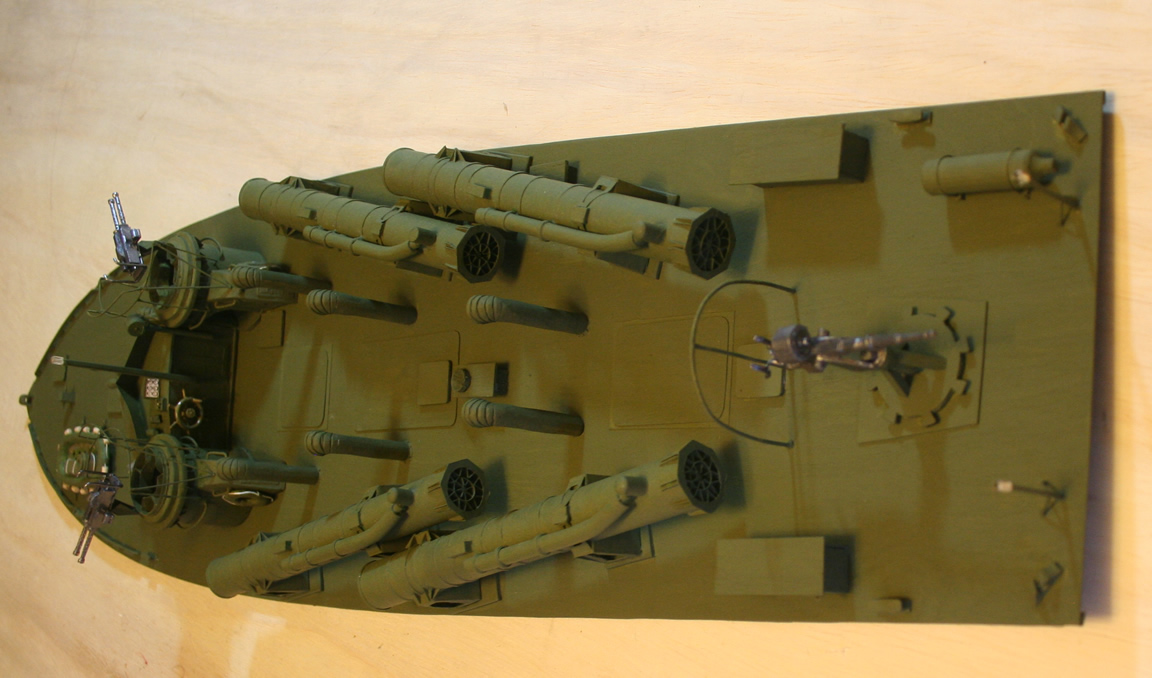
I built a deck for the Higgins hull showing an early Higgins PT boat to illustrate the set up of the torpedo tubes and the design of the pilot house/cockpit with the two adjacent turrets. The torpedo tubes Higgins used were the same Navy design as used on the ELCO boats, but Higgins implemented them differently, positioning them at the proper angle for launching a torpedo and adding the compressed air launching system. The launching system shows as the smaller tube along the top of the torpedo tube iteself.
Here are a few shots of the early Higgins deck in 1:32 scale.
The late Higgins was from builders plans and was built as designed, although by the time the late versions were being built, they were all commissioned with roll off torpedoes and the heavy weapons (40mm, 37mm, 20mm) of late 1943-1944, rather than the two 20mm cannon shown on the plan for this boat. This reflects how the boats were being modified even as they were constructed, so that by 1944 all PTs headed for the Pacific were commissioned with camoulflage paint and all the weapons mentioned above. The larger capacity cranes availble on ship as well as at the delivery points allowed the boats to ship will all the guns installed, although not the torpedoes.
This model was built to show the re-positioning of the turrets after the torpedo tubes had been officially eliminated. It is from builders plans for the PT 462.
Here's a video of the late Higgins on the Bayou. Several issues are apparent. First, the torque of the motor tips the hull noticably. Second, the model lacks the speed needed for the hull to plane and lose the bow wave. Third, the model is small enough that it bobs about on the water like a toy. All three issues are addressed in the larger Higgins model discussed below.
Model of Higgins PT in 1:16 Scale
Experience with the 1:32 scale boat models on the water in Bayou St. John, both the PT series and the Vesuvius, led me to build larger models in the hope that their performance on the water would be more realistic. I was hoping that I could have good RC performance while still maintaining good scale model appearance.
For this project, I decided to model an early Higgins PT boat because I wanted to have the ability to launch torpedoes and thought that would be easier if they were launched from torpedo tubes. After the experience with this model, however, if I built another, I would equip it with roll off torpedoes. This will be discussed later when I describe the torpedoes and their tubes and the launching mechanism I used.
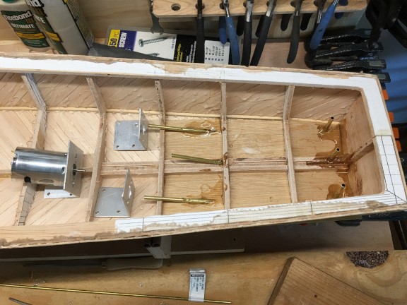
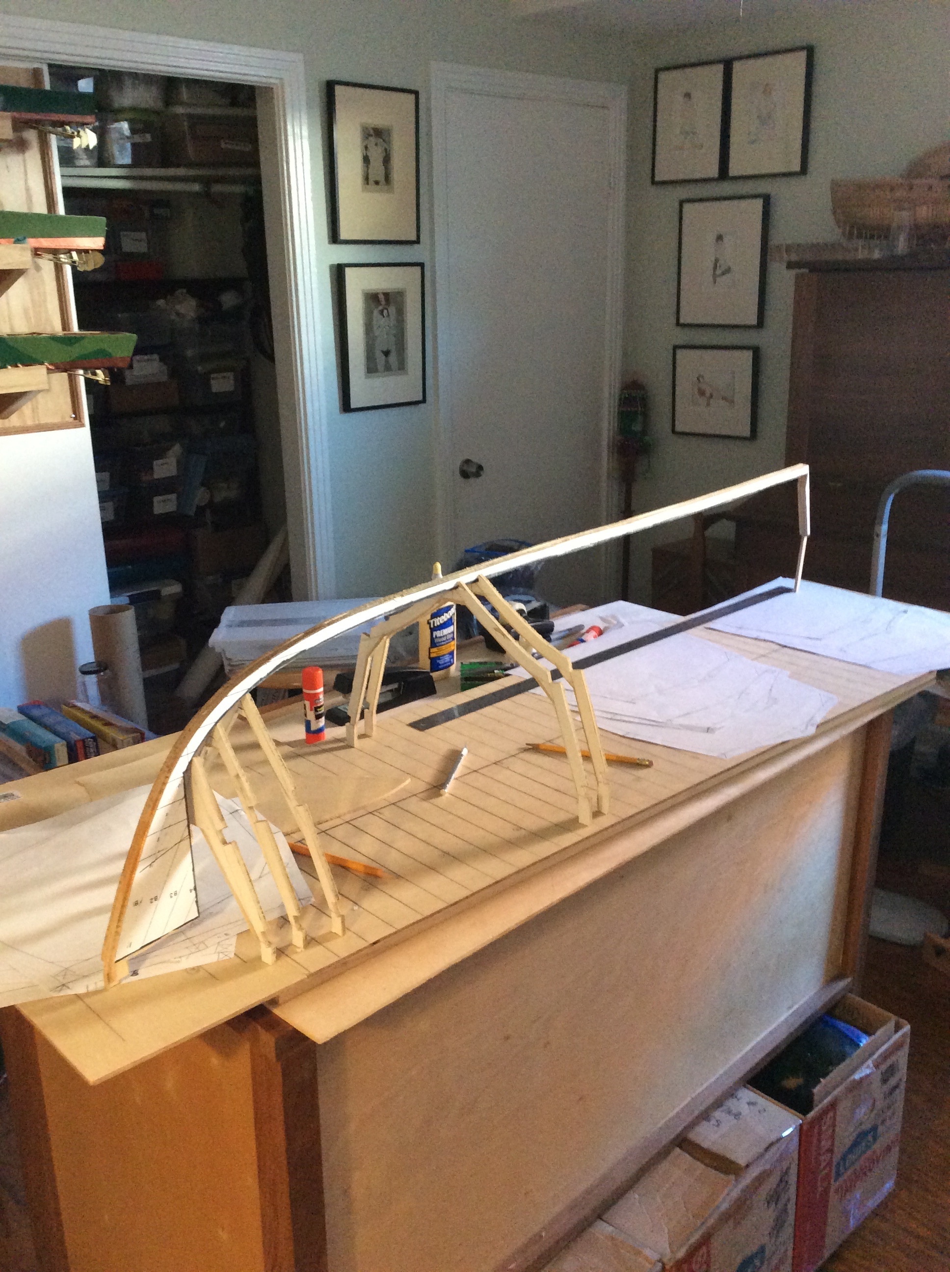
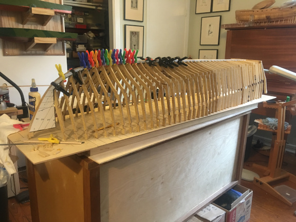
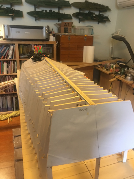
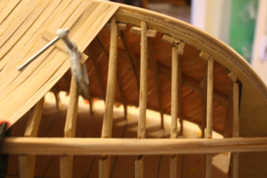
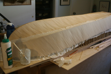
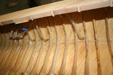
Powering the larger model was also important, as well as weight and buoyancy matters. I built the hull by cutting frames from 1/4 inch lauan plywood, interpolating additional frames between the station sections on the hull plan I was using. Then I planked the hull with white pine planks, 1/16 inch thick by about 1/4 inch wide in two layers, with a layer of cotton fabric impregnated with water proof glue between the layers. The second layer of planks went on in the proper angle duplicating the original Higgins planking pattern. On the smaller Higgins hull, I had planked the same as the ELCO hulls, and this was not correct. I built the hull upside down in a modification of the Harold Hahn method, drawing out the frames to a common horizontal line so they would glue down to a plywood building board to make a solid and rigid base for the planking. Just below are pictures of the hull framing and planking process. After the frames were set up, I added the chine timber, of pine, and later the gunwale plank, also of pine, but laminated up of thinner stock to accommodate the curve of the bow. You can see the large number of frames and the two layers of planking with cloth between. In one shot, with the gunwhale plank in place, you can appreciate the added frame height needed to build this way.
After the hull was planked to the gunwales and the external gunwale added, I varnished the hull with multiple coats of marine spar varnish.
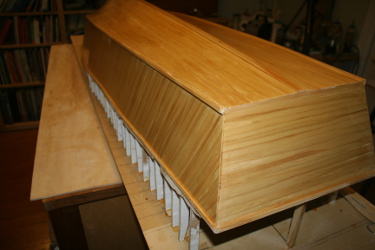
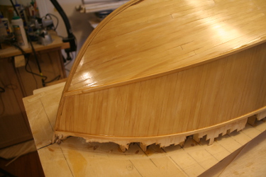
Once the hull was varnished, I cut it free of the building board along the gunwales then made the building board into a cradle for the hull and began work on the inside and on the deck.
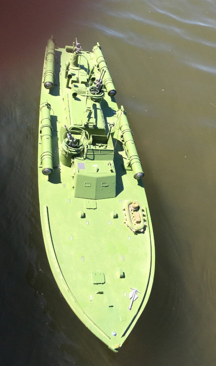
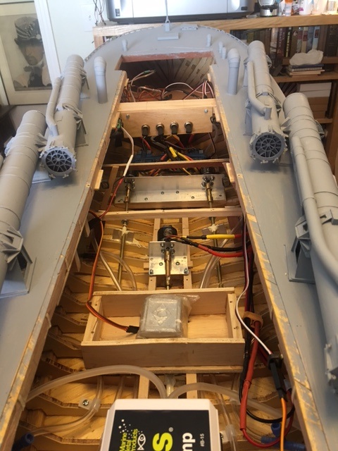
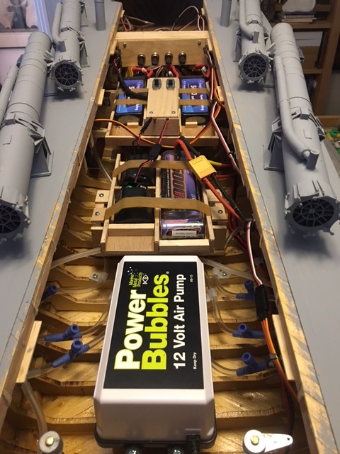
I had decided to power the boat with three powerful outrunner motors, designed for helicopters and drones. They were very lightweight for the power, but needed lots of air for cooling, so I had to allow them plenty of room and add a small fan and also allow air entry into the hull by making the multiple ventilators actually work. Each motor had its own heavy duty, water-cooled speed controller and the three controllers were connected together to the receiver so they worked in unison. The cooling water for the controllers entered through a small forward directed scoop about a third of the way from the bow and exited via a rear directed scoop aft of the entry. The system worked well and the motors performed as hoped. In fact, later, when running the boat for the first trial, the powerful motors sheared the nylon connectors I initially used to connect to the prop shafts and I then substituted soldered brass tubing connectors. The motors did run hot, but never too hot to touch or to present a fire danger. And the boat performed extremely well.
With the motors selected I could place themn, their batteries, and the speed controllers in the hull and do some buoyancy testing. I found that I could add about 20 additional pounds of weight for the hull to float at the appropriate waterline, which gave me lots of options for added equipment and for additional detail. As I worked, I weighed and kept track of what I was building and adding to keep below the upper weight limit for the finished boat.
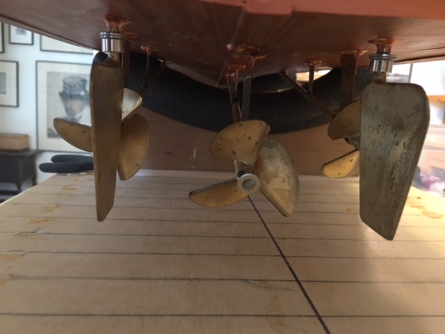
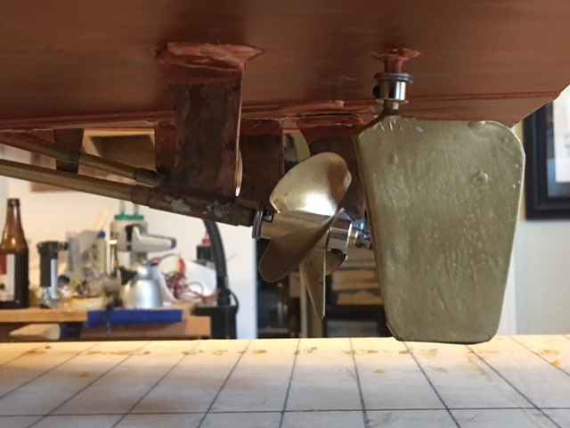
The propeller shafts are 3/16 inch solid brass with stuffing boxes made from brass tubing. The supporting struts were fabricated from brass and epoxied to the hull. Rudders and their stuffing boxes also fabricated and epoxied into the hull. I purchased some plastic propellers of appropriate size and pitch and secured them to the shafts using a pin in the shaft and a retaining collar behind the prop. I painted them with bronze paint.
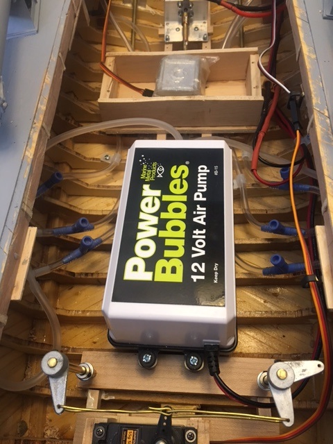
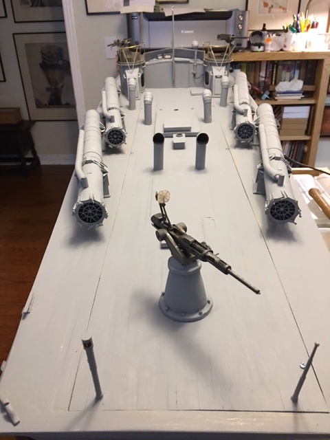
During this phase, I also decided to add an air pump, which would pump air out the exhausts on each side to mimic the bubbling of the exhaust on the Higgins PTs. I carved the exhausts from pine and added a short length of brass tubing inside them. The tubing penetrated the hull when the exhausts were epoxied onto it and then the brass tubing was connected via clear viny plastic tubing to the air pump to be installed much later. I added control valves to regulate the air flow to each exhaust, using aquarium air supply parts.
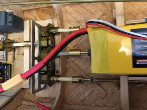
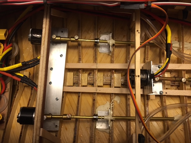
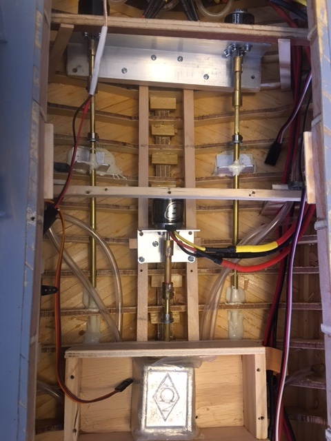
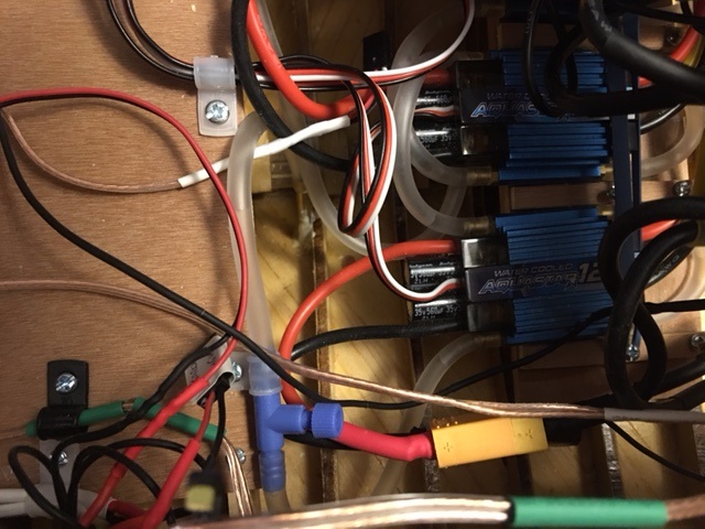
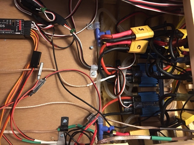
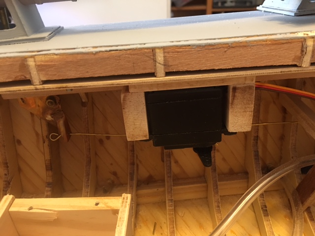
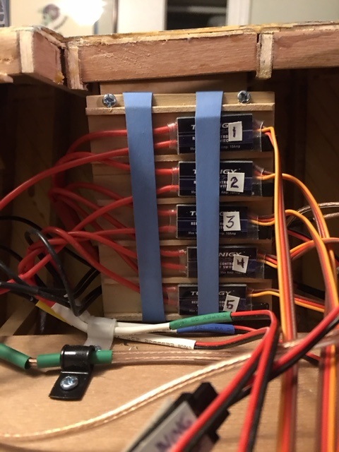
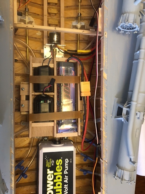
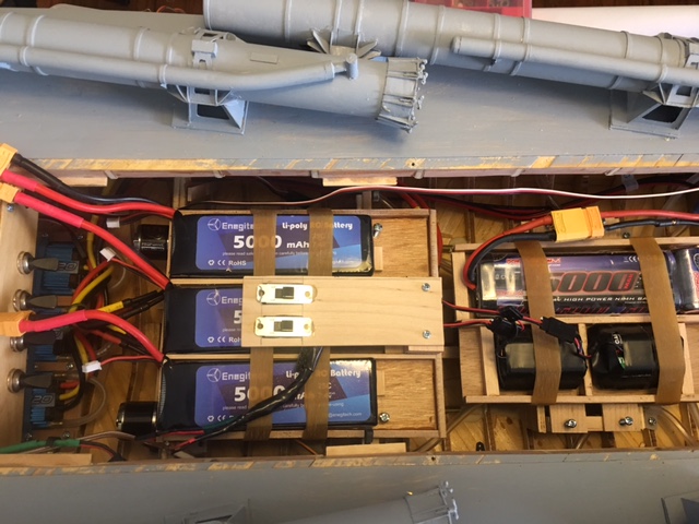
The following pictures are of the hull under construction, the motors, the props and rudders and the air system as they were installed. I also built battery boxes and installed the air pump. Since I planned to add optical fiber to the guns to represent gun flashes and LED bulbs for the various lights, I endeded up with three separate electrical systems, one for the 12 volt air pump, one for the LED lights controlled by an Arduino circuit board, and one for the drive motors (one battery for each). The batteries and controls are pictured in the section below this one.
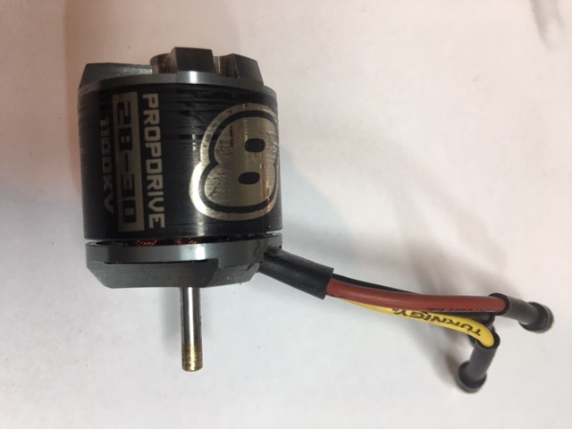
Photos of the motors used in this model, a "PropDrive 28-33", and a picture of the motor mounts, fabricated from aluminum angle. This photo, and the following ones, are taken after the first "sea trial" of the model when the nylon connectors sheared and the boat made it back to shore with one prop running. The connectors in these photos are made of brass tubing. You can also see in these photos that the deck is complete and the deck furniture added. The initial motor, prop, rudder, and exhaust installation was done before the deck was added.
These are the speed controllers, one for each motor. The clear tubing carries the cooling water through each of the controllers. The second shot shows also the 16 channel receiver with the speed controllers connected to it. Early on, as I started to add functionality to the model, it became clear that I needed more channels than a simple 4 channel system. I went to a 16 channel receiver and transmitter, and by the time I was done, I used almost all 16. I found it pretty confusing, however, to manage the transmitter with so many channels, especially when trying to keep an eye on the model in the water.
Photos of props and rudders. You can appreciate the difference in the angle of the center propeller shaft characteristic of Higgins PTs.
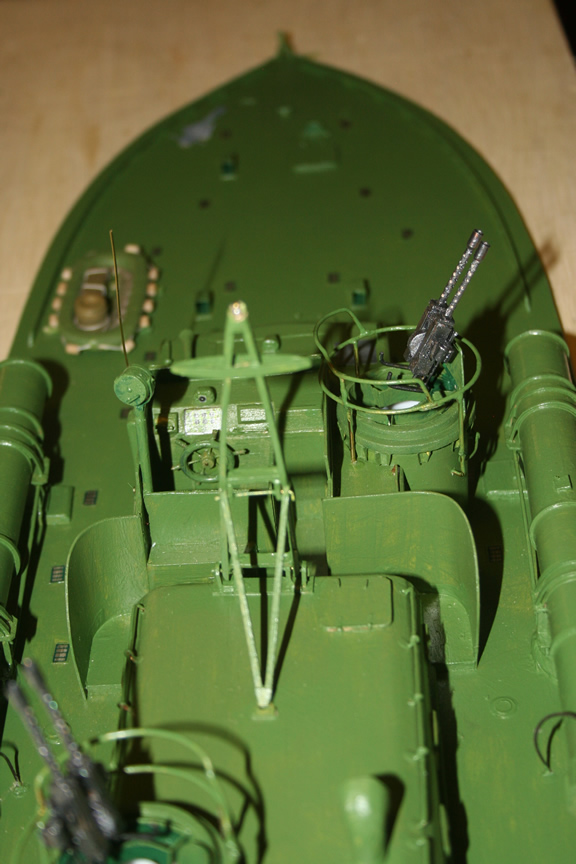
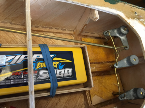
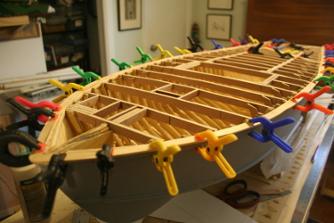
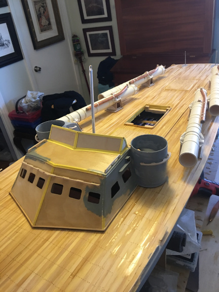
Once I had some of the equipment installed in the hull, I added the deck. First the deck beams, leaving openings for a forward hatch and the pilot house with a large removable deck section aft of the pilot house for access to the hull. Within that removable deck area, I also later modeled the engine room hatch as separately removable for quick access to switches to activate the electrical systems when running the boat. The deck was planked in two layers, using pine planks as for the hull, first a diagonal layer, then a fore-and-aft layer. That way I could build the cabin/pilot house over the first layer, then bring the second layer up to it and could also overlap planks to give a seal along the removable deck area.
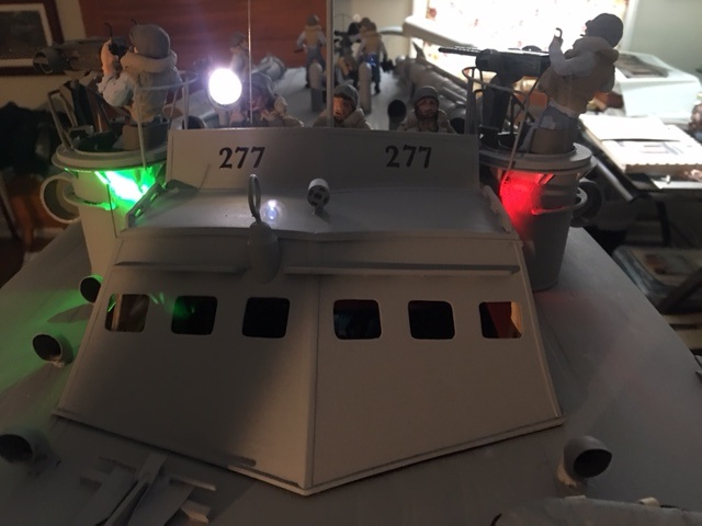
Once the pilot house was built and the second layer of decking laid, I added the turrets and built the wings for the pilot house. These lifted off with the removable deck section and the forward part of the removable section was anchored by having the forward end of the pilot house lock under the opening in the deck. The resulting deck seams were almost invisible. The basis for the turrets was two empty cardboard containers of "Tony Chachare's" Creole spice mix, which seemed appropriate.Here are some photos of the deck and pilot house construction, and the start of the torpedo tube layout.
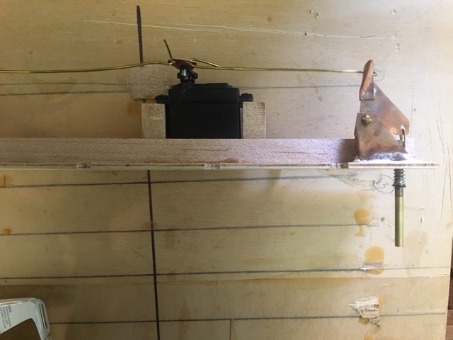
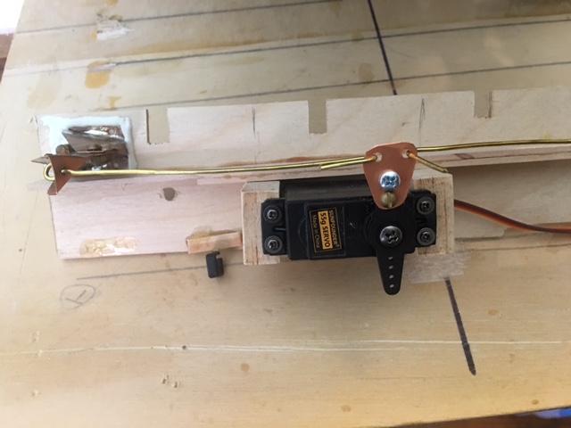
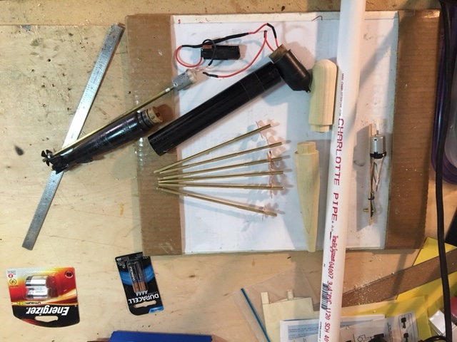
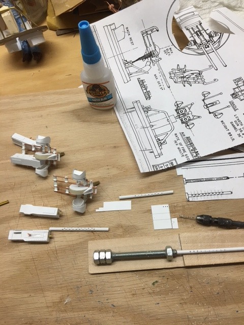
At this point, I was ready to start of sub assembly of the boats armament. I first built the torpedo tubes, using PVC pipe as the basis for them and copper tubing for the compressed air chamber. I designed the torpedoes around the same time and went through several iterations before getting a system I was happy with. The tubes contained large springs anchored to the back of the tube with a disc on the other end about three quarters inch in diameter. The torpedo was inserted into the tube, compressing the spring and then anchored with a one eighth inch brass pin that came up through the deck through the bottom of the tube and to a notch in the underside of the torpedo. I ran the pin into the tube through one of the two mounting brackets for the tube so the pin was nearly invisible except to someone looking for it. The pin was attached to a rocker arm that was controlled by a heavy duty servo. When the servo was activated, the pin moved down and the torpedo launched. I used one servo on each side to control the two torpedo tubes on that side. I set the rocker arm that connected to the pin with a wire that only pulled the arm and could not push it, so that working the servo one way and then the other could launch both torpedoes on that side. If I were doing it again, I would model a Higgins with roll off torpedos and have a similar mechanism that simply pushed up to tip the launching rack up and launch the torpedo rather than using tubes and a pull pin.
All that said, the design of the torpedoes took some time. I experimented with different motors and many batteries before coming up with the final design.
The propellers were hand made of brass and soldered to a 1/8 brass rod that ran through a brass tubing sleeve into the back of the torpedo, which was lathe- turned from wood. It has fins of plastic glued to it. This back part slip fit into a piece of plastic tubing containing the motor and battery and a "reed switch" which was the middle part of the torpedo. The nose cone of the torpedo was also of wood and slip fit into the plastic tube. At the tip it carried a home made sliding switch of brass tubing which was "on" when the tubing was fully extended and "off" when it was pushed back into the torpedo. The concept was that the torpedo could be loaded into the tube with this switch "off", then once in place, activated by pulling this switch out to activate it. (see more about the reed switch below) In the unlikely event the torpedo would actually hit a target if launched, the switch would be pushed in to turn off the motor.
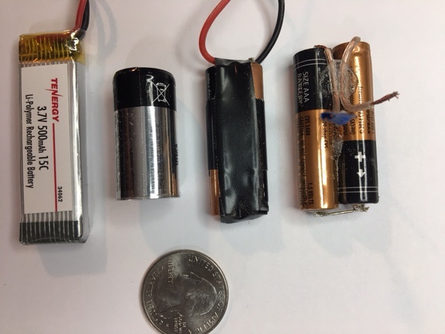
Finding a suitable battery took a while but ended with a 3.7 volt rechargable lithium battery, which worked splendedly.
The next key element was the reed switch. These tiny switches are operated by an external magnet and are used commonly in home security systems where they are installed on one side of a door or window edge with a magnet on the other side so that opening the door or window turns on the switch and signals the alarm. The switches can be wired as either on or off. If wired off, the magnet activation will turn them on and vice versa. I used them wired to be on unless a magnet was nearby, then they would turn off. By wiring a reed switch into the motor power lead from the battery and placing the reed switch on the bottom of the torpedo at the front of the plastic section and placing a strong button magnet on the underside of the torpedo tube at a corresponding location, I could turn the torpedo off when it was placed in the tube.
The routine of loading the torpedo became rather simple. I pushed in the nose switch of the torpedo to the off position. Connected a charged battery to the wiring and assembled the torpedo, using a length of black viny tape over the seams to seal them. Then, with the deck of the boat removed, I reached in with needle nose pliers and pulled the firing pin down so I could slide the torpedo into the tube. Once I felt the pin seat into the notch in the torpdeo it would stay in place. Then I pulled the torpedo nose switch out. The motor would not run as the magnet on the bottom of the tube turned the reed switch off. When the torpedo was launched by pulling the pin, as it left the tube and the magnet, it started running.
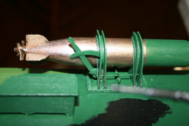
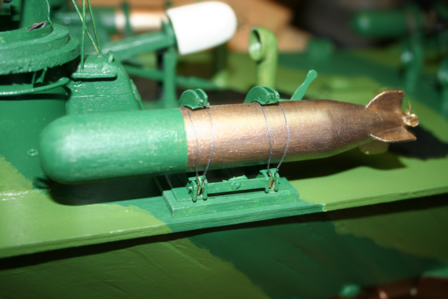
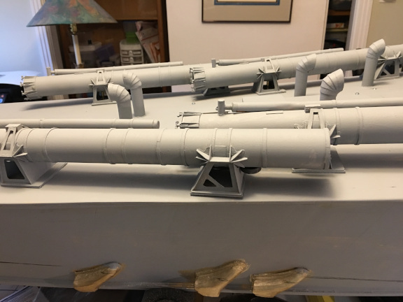
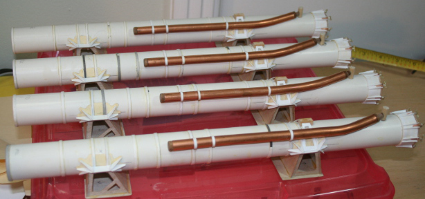
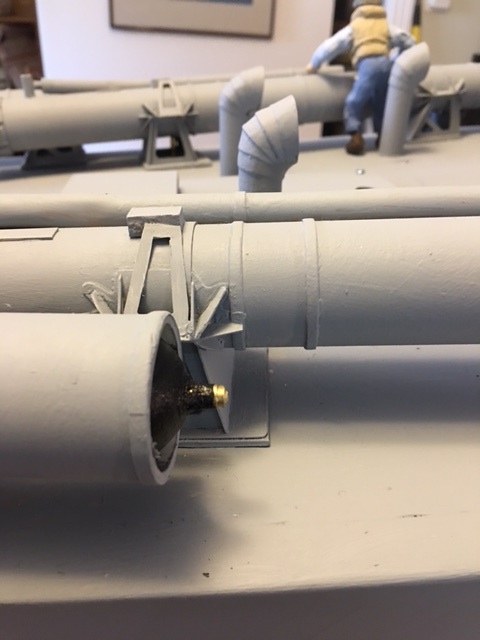
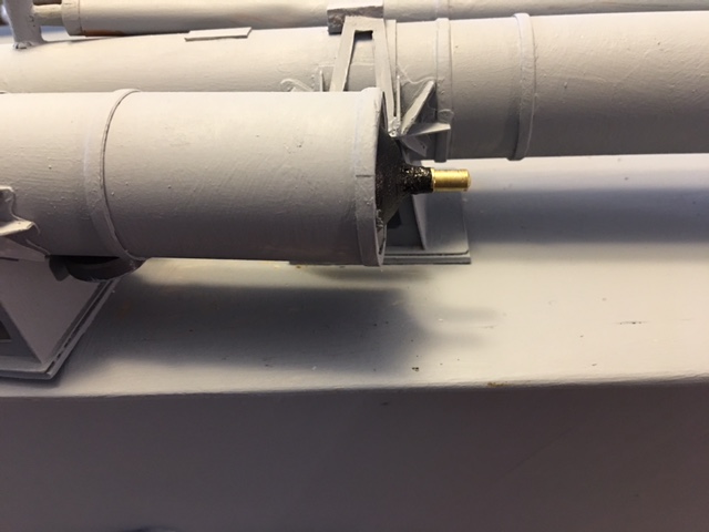
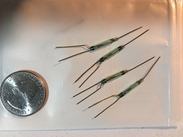
Following are a series of pictures of the torpedos and their evolution as well as a couple of shots of the torpedo tubes.
Torpedo tubes under construction.
The launch firing pin and its servo.
The torpedo placed in the tube. Intially disarmed, then armed.
Torpedo construction and evolution.
The slide switches used to arm/disarm the torpedo.
Here is the rear section of the torpedo. You can see the projecting notch that the firing pin seats against in both pictures. The second picture shows both the first version and the second version. The second version was shorter and provided more space in the plastic mid section.
And the two parts that were invaluable in making a suitable torpedo, the magnetic controlled reed switch and the Lithium battery. The photo of the batteries shows all that were tried in the torpedo evolution.
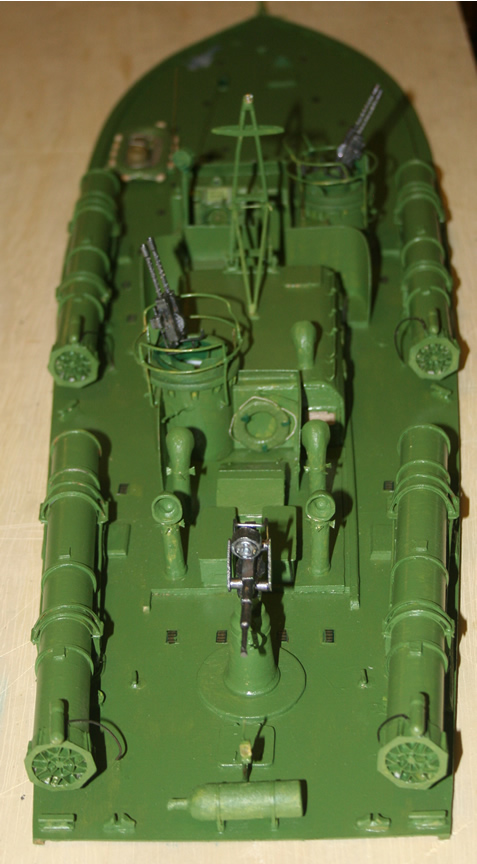
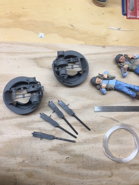
And now for a somewhat random selection of photos of construction of guns and the making of the crew. And a few of the lights installed in the model.
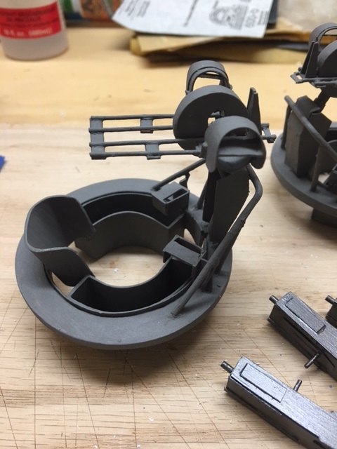
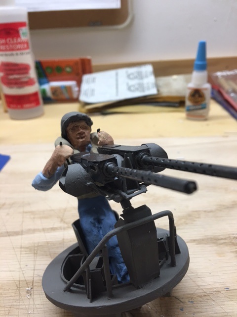
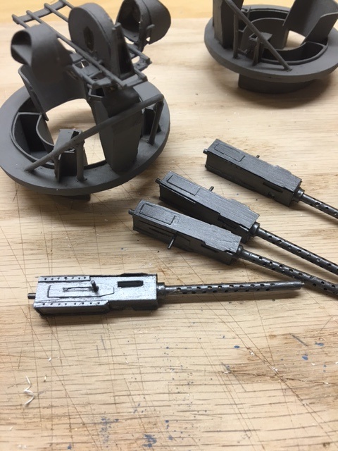
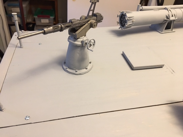
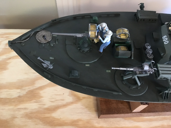
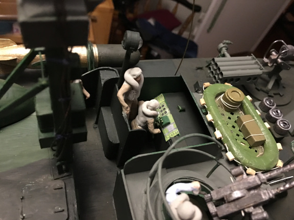
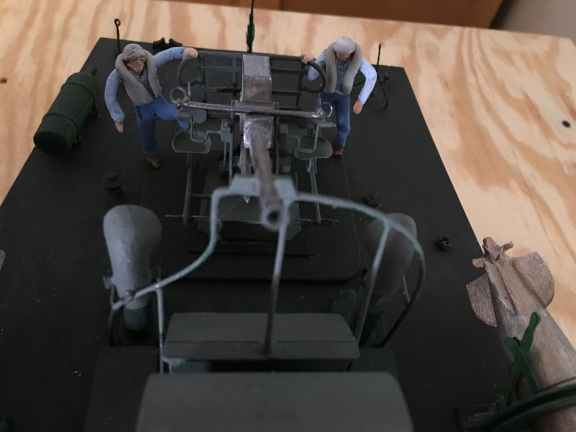
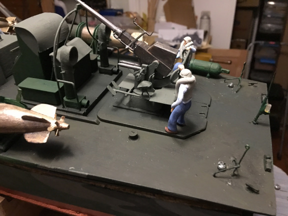
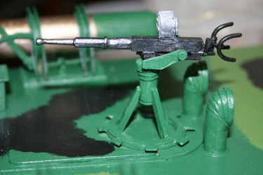
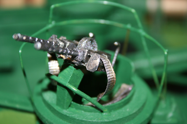
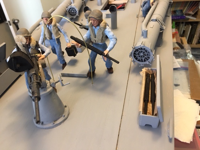
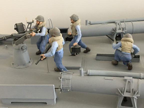
The 20 mm Oerlikon auto cannon was modeled with optical fiber in the barrel illuminated by a red LED bulb below the deck. The gun crew is shown having just replaced the barrel. One crewman, wearing asbestos glove, is putting the used barrel into a water bath to cool it before stowing it in the box containing more barrels along the starboard side by the gun mount. A second crewman stands holding another barrel at the ready. Oerlikon barrels were to be swapped out after firing about 9,000 rounds or less and the cannon fired in a fully automatic fashion when the trigger was down at a rate of about 250 to 400 rounds per minute. In a long engagement, the barrel might therefore need replacement, a process that took about 30 seconds. Ammunition was stored in drums holding 60 shells. The loader is carrying two magazines to the gun from the ammunition storage box forward of the gun.

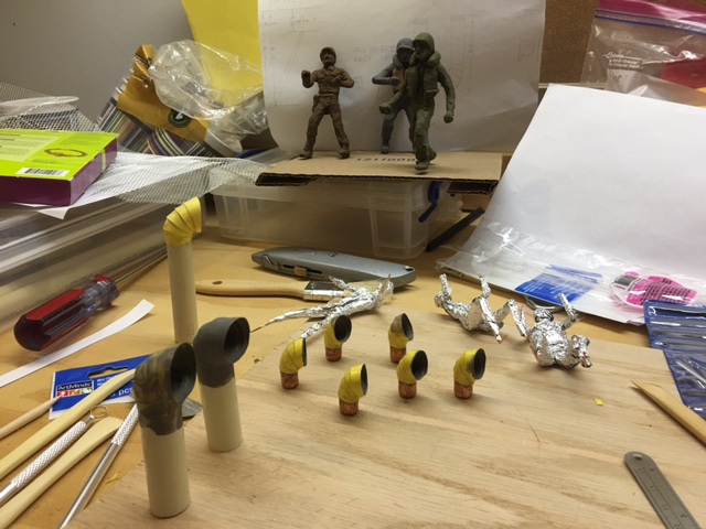
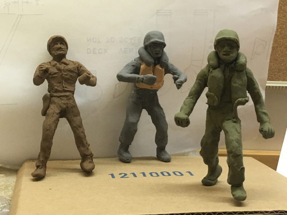
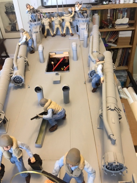
Following are some photos of the crew being modeled from heat-setting polymer clay over armatures of copper wire and aluminum foil. The first picture also shows the working ventilators under construction. The second shows the clay of the oerlikon gun crew.
Then there are pictures of the crew painted and installed on the boat. There were three officers in the cockpit, dressed in Khaki uniforms, and eight crew dressed in denim. Four men worked the 20 mm cannon, there were two machine gunners in turrets and two torpedomen at their stations. The two or three motormen were below deck.
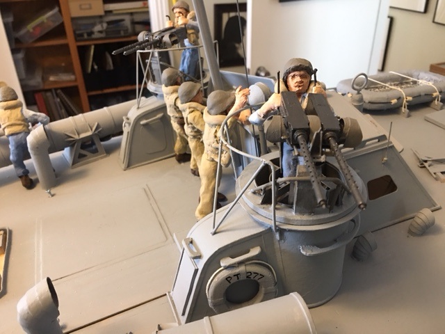
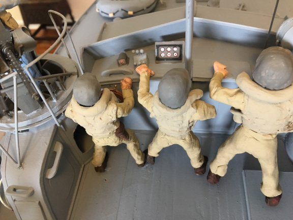
There were LED lights with optical fiber in the 20 mm cannon and both machine guns. There was an LED light in each of the running lights - the red port sidelight, the green starboard sidelight - the bow light, the stern light, and the masthead light with a separate LED in the search light. All these were separately controlled so it was possible to turn on just the running lights or just the mooring lights or just the search lights. There was even optical fiber illuminating the cockpit instruments in red light for night running. You can see the lighted instruments in the photo of the cockpit crew above.
Here some pictures of the lights turned on. In addition, the Arduino controlled the gun LEDs and the search light as is shown in the video below.
As things on the model got more complex, I had added an Arduino board installed in the pilot house to run simple programs controlling the lights. It would fire the machine guns and the 20 mm cannon and then use the signal light to send a message.
Because there were many lights to control in different patterns and because I did not want the Arduino program to run all the time or in all situations, I added some radio controlled switches to turn off and on the Arduino, the running lights, the mooring lights, and so forth. These RC switches are shown in picture below.
There were also toggle switches just beneath the engine room hatch to turn battery power on to each of the three motors and to the air pump as well as small slide switches to turn on power to the LED lights and the RC switch panel.
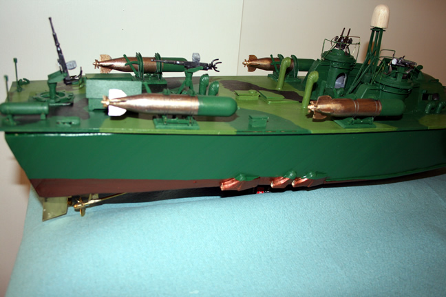
And finally, a video of the model on the water, a video of the guns "firing" as controlled by the Ardiuno, a video of the exhaust bubbling away, and a video of a torpedo in the water. The torpedo, by the way, was highly realistic in that it ran in a circle and did not hit anything.
In 1941 the Navy Department held competition trials known as the "Plywood Derby". These trials included the initial designs from the three private companies competing for the contract as well as a boat designed and built by the Navy. Several other boats designed by the Navy were omitted from the competition because of already known poor performance.
The following boats were tested off New London, CT, fromn 21 to 24 July 1941:
PT-6: 81 ft Higgins; 3 Packard 1,200-hp engines.
PT-8: 81 ft Philadelphia Navy Yard; aluminum hull; 2 Allison 2,000-hp engines, 1 Hall-Scott 550-hp engine.
PT-20: 77 ft Elco; 3 Packard 1,200-hp engines; special propellers;strengthening added to framing and deck.
PT-26, -30, -31, -33: Elco: Same as PT-20, with standard propellers and without strengthening.
PT-69: 72 ft Huckins; 4 Packard 1,200-hp engines.
PT-70: 76 ft Higgins; 3 Packard 1,200-hp engines.
British Design 70 ft built for Britain by Higgins; 3 Hall-Scott 900-hp engines.
The test included an open-sea run of 190 miles (310 km) at full throttle, giving rise to the nickname "Plywood Derby." The course started around New York Harbor, at Sarah Ledge, then led around the eastern end of Block Island, then around Fire Island Lightship, finishing at Montauk Point Whistling Buoy.
At the completion of the trials, the Navy considered all three designs and awarded contracts to all three private companies that competed. The Navy attempts as their own PT boat designs ended with these trials. The Elco 77-footer (PT-20) came in first with an average speed of 39.72 kn (45.71 mph), followed by the Huckins 72-foot boat (PT-69) and the Higgins 76-footer (PT-70). By the end of the war, Elco received the largest share of contracts (350 boats), Higgins contracts for 199 boats, and Huckins a contract for 18 boats.
There were several significant differences between Higgins PT boats and the ELCO boats. Although both manufacturers were required to incorporate some standardized equipment supplied by or built to Navy specifications, such as the torpedoes and torpedo tubes, the machine guns and their mounts, smoke generators, and later the cannons, each company implemented use of the standard equipment differently.
In the ELCO boats, torpedo tubes were mounted parallel to the side of the boat. In order to launch a torpedo, the tubes had to be manually cranked outward at the forward end, so the torpedo would clear the edge of the boat when launched.
In the Higgins boats, the four torpedo tubes were mounted at an angle to the long axis of the boat so they were already in position to launch the torpedo and did not need any change in position during operations.
The ELCO boats launched their torpedos with a black powder charge. In photos of these boats, and in the models shown here, this charge is contained in a small canister on the top of the after end of the torpedo tube. The black powder was ignited by an electric discharge transmitted by wire from controls in the cockpit. This method of launching torpedos produced a large flash when the powder ignited, revealing the position of the PT boat, especially at night. Also, since the torpedoes were coated with grease when installing them in the tubes, sometimes a fire in the tube resulted from the grease igniting when the powder discharged, further revealing the PT position and requiring crew to put out the fire. The system of electrical ignition of the powder was also not entirely reliable, and when a torpedo launch was planned, a torpedo-man stood by with a large wooden mallet to strike a manual igniter at the back of the powder canister if needed.
The Higgins boats launched torpedos with compressed air, and thus had no position-revealing flash upon launch. These boats used the same torpedo tubes as the ELCO boats, but instead of the powder canister carried a smaller secondary tube along the top of the torpedo tube for the compressed air, supplied by an on-board air compressor.
Engine rooms were relatively small on PT boats making the installation of three Packard Marine V-12 engines difficult and the servicing or replacement of the engines in the field similarly difficult. ELCO solved the problem of fitting the third engine into the space available by mounting the center engine backwards, using a reversing drive transmission to transmit that engines power to the center propeller shaft. Higgins solved the problem by mounting the center engine higher than the side engines and having the center propeller shaft enter the water at a steeper angle so that the center prop was lower and slightly behind the side props. Engine removal on the ELCO boats required the removal of all or part of the main cabin structure. On the Higgins boats, there was no raised main cabin and the engine room had a separate easily removed hatch for access to engines.
ELCO routed engine exhaust to the transom of the boats. There were six exhaust pipes exiting the transom above the water line. These pipes had manually controlled dampers that diverted the exhaust into downward directed pipes leading underwater for quiet running. The 77 foot boats had simple pipes leading underwater; the 80 foot boats added mufflers which exited below the waterline. Higgins routed engine exhaust to the sides of the boats. There were three bronze exhaust ports below the waterline beside the engine room on each side of the boat. The exhaust therefore always entered below the waterline so there was no need to manually switch over the discharge for quiet running.
The ELCO boats had three rudders. The Higgins boats had two.
The first ELCO boats were designed with the helmsman stationed within the pilot house, receiving direction from the skipper either in the pilot house too or in the "cockpit", an open area just behind the pilot house, also equipped with a wheel and duplicate controls, which was accessed by climbing over the side of the pilot house and down into the cockpit. They also had hydraulically controlled plastic-glazed turrets each with two 50 caliber aircraft type (air cooled) Browning machine guns. Very quickly, crews in the Pacific, where the boats were first deployed, removed the turret glazing and hydraulics, switched operation of the boat to the cockpit controls, and painted over the windows in the pilot house to eliminate light reflection during night operations.
The Higgins boats and the later ELCO 80 foot boats mounted wheel and controls on the after wall of the pilot house the sides of which extended back to form a sort of cockpit with an open back directly accessible from the deck. The pilot house, in later boats, housed the more advanced radio and radar electronics available beginning in 1943. In most cases, pilot house windows were painted over or covered with canvas or other material to prevent light leakage or reflection during night operations.
The ELCO boats positioned the pilot house a bit further back on the hull, making more room forward of the house for (later) installation of additional weapons. The 77 foot ELCO had the two gun turrets mounted on the sides of the main cabin, well aft of the cockpit. On the 80 foot version, one turret was just beside the cockpit on the starboard side, and the second was at the after end of the main cabin on the port side. The ELCO turrets were accessed from inside the cabin or the pilot house. In heavy seas, water splashing up and into the turrets could enter the cabin. Most ELCO boats had canvas splash cloths installed around the turrets to prevent this. The Higgins boats mounted the turrets just behind the open cockpit. The gunners accessed the turrets through an opening at the deck level inside the cockpit area. Any water entering the turrets simply flowed out onto the deck. Early Higgins boats mounted the turrets close behind the cockpit. Later boats, after removal of the torpedo tubes, moved the turrets back several feet which improved visibility from the cockpit. In the later version, access to the turret remained the same.
Most of the ELCO built boats served in the Pacific theatre. Most of the Higgins boats served in the Mediterranean and English Channel. One of the reasons that more Higgins boats survived the war was that after the surrender of Germany, some of the PT boats operating in England and the Mediterranean, mostly Higgins boats, were shipped back to the US to be reconditioned for service in the Pacific in the continuing war with Japan. Some of these boats in transit survived, whereas the PT boats operating in the Pacific, largely ELCO boats, were destroyed after the surrender of Japan.
Information on modeling the guns and torpedoes and finished photos
One advantage when making the 1:32 scale PTs was that the equipment on the boats was standardized, either supplied by the Navy to the builders or built by third party supplies to Navy specifications. That meant that all the torpedoes and torpedo tubes were the same, as were all the guns, from the 50 caliber Browning machine guns through the 20 mm and 37 mm cannons to the Bofors 40 mm cannon. The mounts for the guns did vary by manufacturer as did the torpedo tube mountings, but the basic components were the same. That was also true for life rafts, anchors, life jackets, and other small equipment.
So to make three early PT boat, I needed to make twelve identical torpedo tubes. For the late boats, the 77 footer carried no torpedoes and the 80 foot and Higgins boats had four torpedo racks each with torpedoes. And so forth. I needed to make lots of machine guns and several different cradles for them as well as differing turrets for specific boats. Similarly I needed multiple 20 mm and 40 mm cannons, but only one 37 mm cannon.
It was easy to set up assembly lines for each item and make as many as I needed and a few extras all at the same time. Often before the deck for which they were intended was complete.
The guns were all built pretty much the same way, with barrels and magazines carved from rock maple and then embellished with brass and cardstock as needed. The 37 mm cannon had a lot of metal work on it as the basic gun was very simple but the magazine and ammunition canister was complex. I assembled some of the metal parts with soldering when possible and sometimes with cyanoacrylate glue. The CA glue was used to attach the metal and cardstock parts to the wooden parts. Pedestals and mounts were modeled from wood and cardstock. Sometimes, as with the 40mm mounts, entirely from cardstock. Magazines for the 20 mm cannon were from wood. For the 37 mm cannon from brass.
Turret tops and machine gun mounts were made from balsa, maple, brass and cardstock and differed for each class of boat.
Below are a few pictures of the "assembly lines".
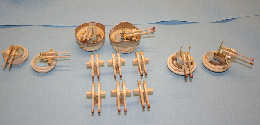
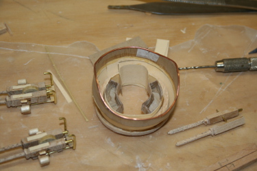
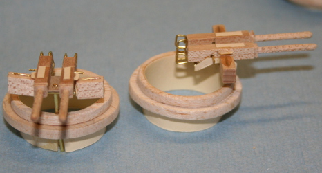
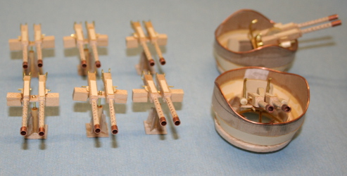
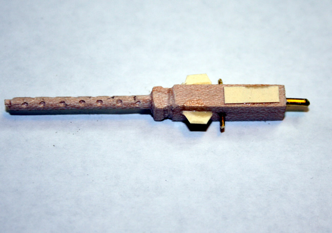
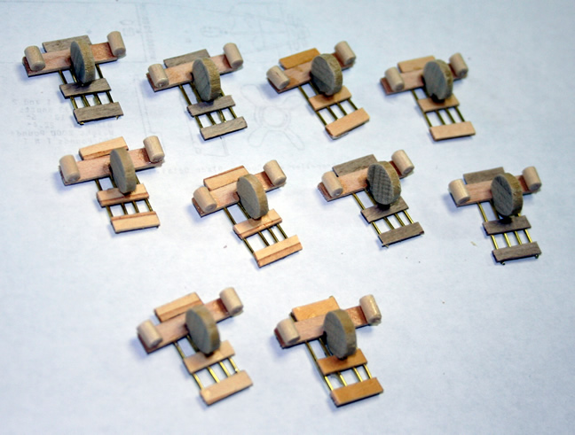
The torpedo tubes were formed from rolled paper formed over one half inch copper pipe. The end caps were also paper and cardstock and the reinforcing fins and fasteners of the caps were made from plastic and cardstock.
Pictures of the torpedo tube assembly line.
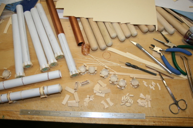
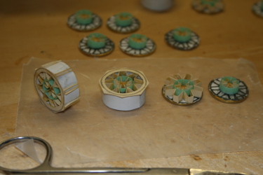
The roll off torpedoes were easy to make. The roll off launching racks were harder. I had to find good plans for the actual racks, and once I had them, it was relatively easy to model them in thin brass sheet with on a balsa base. Once the racks and torpedoes were painted, the torpedoes were placed in the racks and held with a fine gray thread to represent the retaining cable on the actual rack. These "cables" passed around the torpedo and were held by brass fittings on the end which in turn were held by small brass pins. When the torpedo was launched on a PT boat, the torpedoman moved the lever which pulled the pins holding the cable, and the torpedo rolled off the rack.
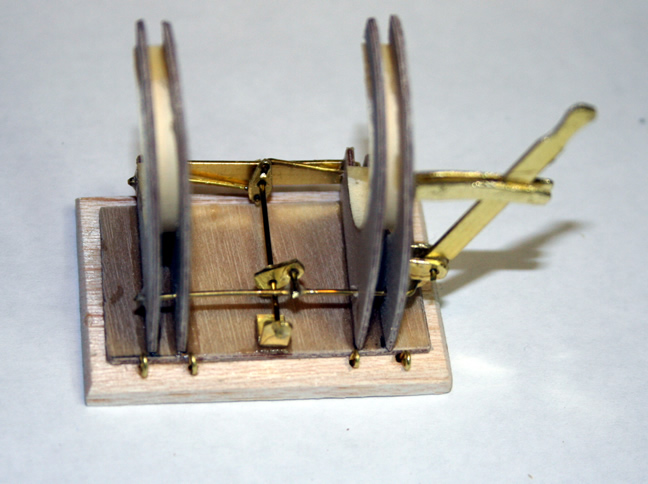
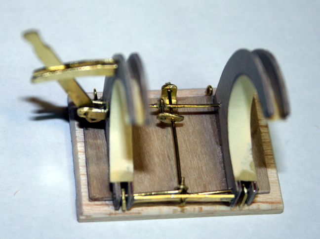
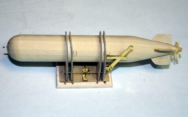
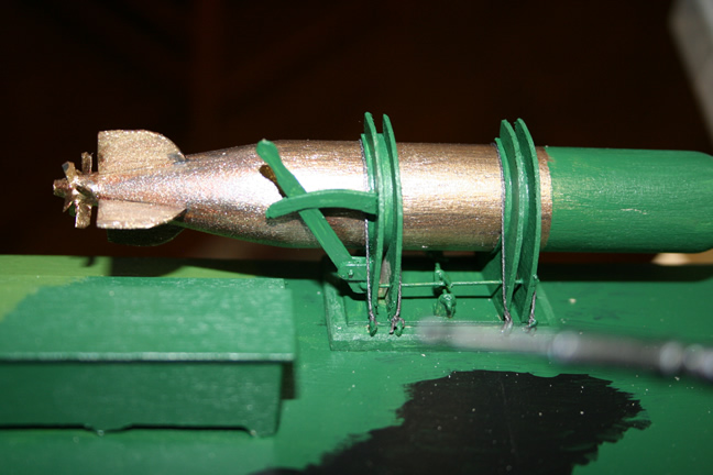
The basic Bofors 40 mm cannon was carved from hard Maple and then embellished with brass, wood, and cardstock parts. The gunners' seats were moulded from moistened cardstock. Each of the Bofors cannons had a different mount so these were created for each boat. The basic cannon was the same on each. The covers for the ammunition feed on the top of the guns was covered by a cardstock cover except for one in which the cover was left off and the guides for the shell clips were shown.
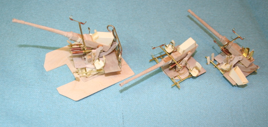
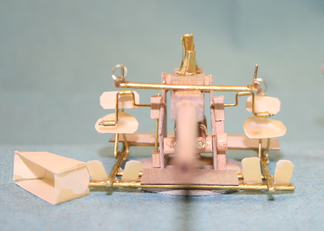
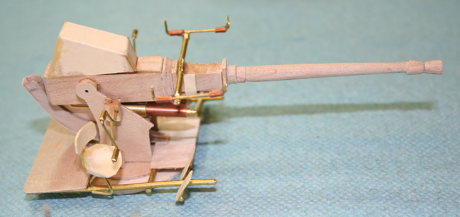
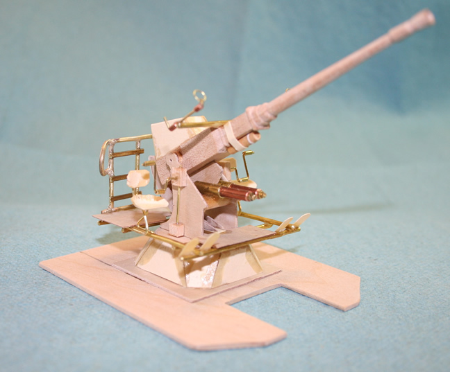
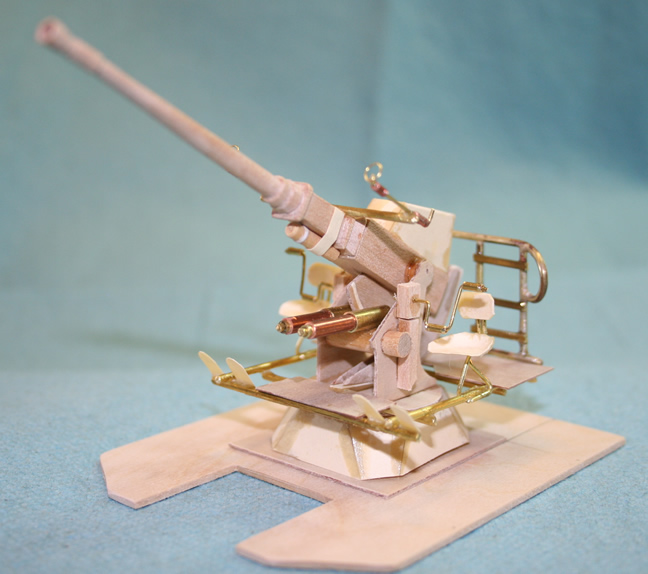
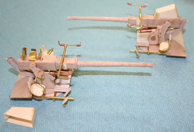
There was not much to carve up for this gun barrel. All the work was in making the special ammunition holders. I made them up of sheet brass and some exceptionally fine brass screen. The pedestal mount was fabricated from carved maple and thin birch plywood. The extra ammunition and shells were stored on the deck of the model that eventually became PT 600.
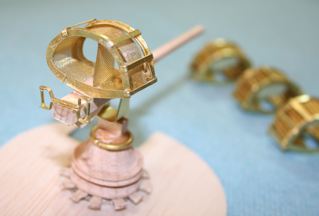
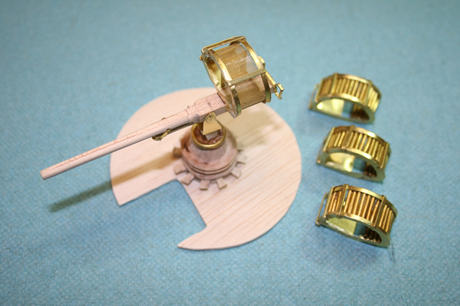
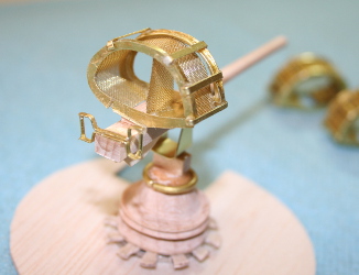
The 20 mm cannons were made the same way, starting with a carved Maple barrel and chamber, then adding wood, brass, and cardstock parts. Again, there were different mounts for these guns. A simple solid pedestal on early ELCO 80 boats and open mounts on later and other boats.
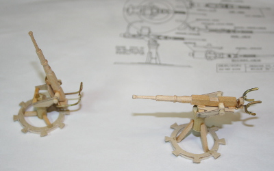
Life rafts were carved from balsa for the outer ring covered with silkspan to represent canvis and a fine plastic mesh from vegetables sold at the grocery store for the netting. The platform is from thin wood strips. The life ring is held on the ring by thin paper strips and the cork floats are cut from thin wood dowel and drilled for the "rope".
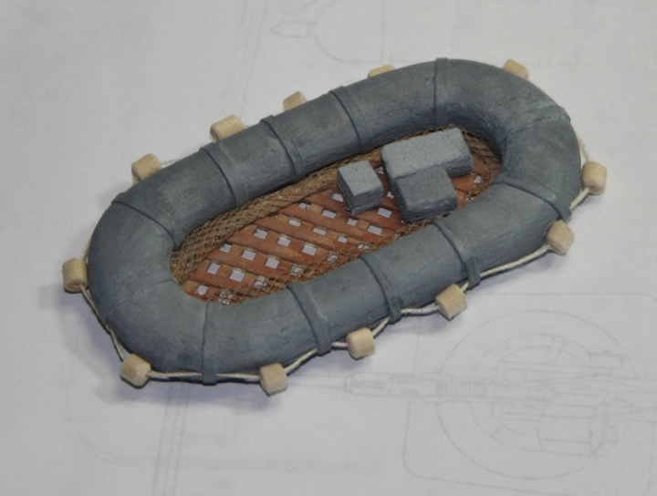
Here are two photos of the late ELCO 80 model. First as it was originally built as the PT 596 (526 class), and second as it was modified into the PT 600.
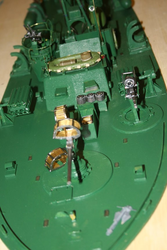
PT Boat Armament and Evolution
Initially, Navy contract specification required PT boats to all carry four torpedoes, Mark 8 torpedoes, which weighed 2,600 pounds, contained a 466-pound TNT warhead, and were launched by Mark 18 21-inch steel torpedo tubes, each of which weighed about 1,450 pounds. Mark 8 torpedoes had a range of 16,000 yards at 36 knots (41 mph). These torpedoes were essentially left over from WW1 and were notoriously unreliable, tending to not run true, to not run at set depth, and to run in circles. They also were frequently "duds", failing to detonate even when striking a target. The development and deployment of these torpedoes is an interesting story for another time, but at the time the Navy was developing PT boats, it was pretty much committed to using launch systems that had been developed for destroyers and required launch tubes and required them on the PT boats, adding significantly to the weight the vessels carried. Each tube when loaded with a torpedo weighed just over two tons for a total of eight tons of weight.
Although the torpedo tubes used were the same on both ELCO and Higgins boats, the two manufacturers implemented them differently. These and other differences between the two types of boats are discussed in the section on PT boats as gun ships operating against barges or as on-shore attack vessels, all or some of the torpedos were replaced with more cannons and machine guns, depth charges, and even mortars.
With the elimination of the torpedo tubes, the hulls also evolved somewhat as results from experiments with weaponry in the field were incorporated into the manufacture of subsequent boats. See Differences for more discussion.
From the beginning, PT boats were also well armed with numerous automatic weapons. Common to all US PT boats were the two twin M2 .50 caliber machine guns mounted in turrets. Early 77 foot PT boats (Elco PT20 through PT44) mounted Dewandre plexiglas-enclosed hydraulically operated rotating turrets. Almost immediately after the attack on Pearl Harbor, the Dewandre turrets were replaced on the entire PT boat fleet with open ring twin mounts. The ring mount was designed by both Elco and Bell, and designated Mark 17 Twin 50 caliber aircraft mount. It included the Bell Mark 9 twin cradle holding the guns themselves. The first series of 77 foot boats also had two Lewis guns mounted on the fore deck.
Reports from the field quickly resulted in the addition of heavier guns. Another automatic weapon commonly mounted on PT boats was the 20 mm Oerlikon auto-cannon. When it first was added to the boats, this cannon was mounted on the stern. Later in the war, several more of these 20 mm cannons were added amidships and on the forward deck. At least one squadron (RON 9) in the Pacific experimented with a single 20 mm cannon mounted in the forward turret, replacing the 50 caliber machine guns in the ELCO 80 boats on an experimental basis. Crews were encouraged to experiment with changes in the weaponry.
Forward of the chart house of some early Elco 77-foot (23 m) boats (PT20 through PT44) were twin .30 cal Lewis machine guns on pedestal mounts. Beginning in mid-1943, some boats were fitted with one or two .30 cal Browning machine guns on these pedestal mounts or additional mounts forward of the torpedo tubes.
Occasionally, some front line PT boats received ad hoc re-fits at forward bases, where they mounted such weapons as 37 mm aircraft cannons (scavenged from scrapped Aerocobra P-39 aircraft), rocket launchers, or mortars. When these weapons were found to be successful, they were incorporated onto the PT boats as original armament.
One such field modification was made to Kennedy's PT-109, which was equipped with a single-shot Army M3 37mm anti-tank gun that her crew had commandeered; they removed the wheels and lashed it to 2x8 timbers placed on the bow the night before she was lost. The larger punch of the 37mm round was desired because the boats were increasingly being used against the Japanese barges that were used in inter-island resupply in the Solomons. These barges had a drop down ramp on the bow, which ramp was armored, and the operators of the barges had learned to keep the bow toward an attacking PT boat to deflect the machine gun fire. The armor was also effective against the 20 mm cannon, at least at the range the boats normally operated, so the PT crews wanted something with a greater punch than the 20 mm Oerlikon. The 37 mm cannon was promising, but the crews looked for something that could fire faster than the single-shot army anti-tank weapon. Their answer was found in the 37mm Oldsmobile M4 aircraft automatic cannon cannibalized from crashed P-39 Airacobra fighter planes on Henderson Field, Guadalcanal. After having demonstrated its value on board PT boats, the M4 (and later M9) cannon were builder-installed on PT Boats. The M4/M9 37mm auto cannon had a relatively high rate of fire (125 rounds per minute) and large magazine (30 rounds). These features made it highly desirable and popular with crews due to the PT boat's ever-increasing requirement for increased firepower to deal effectively with the Japanese barges, immune to torpedoes due to their shallow draft, with armored ramps on the bow. By the war's end, most PTs had these weapons.
The installation of larger-bore cannons culminated in the fitting of the 40mm Bofors gun on the aft deck of PT boats at the time the boats were commissioned. Starting in mid-1943, the installation of this gun had an immediate positive effect on the firepower available from a PT boat. The Bofors cannon had a firing rate of 120 rounds/min (using 4-round clips) and had a range of 5,420 yards . This gun was served by a crew of 4 men, and was used against aircraft targets, as well as shore bombardment or enemy surface craft.
Towards the end of the war, beginning in 1945, both the ELCO and Higgins PTs mounted two eight-cell rocket launchers on the fore deck. These launched 5 in spin-stabilized flat trajectory rockets with a range of 11,000 yards. Sixteen rockets plus 16 reloads gave them as much firepower as a destroyer's 5-inch guns. By war's end, the PT boat had more "firepower-per-ton" than any other vessel in the U.S. Navy.
PT boats also commonly carried between two and eight depth charges in roll-off racks. Sometimes they were used as a last-ditch weapon to deter pursuing destroyers. The depth charge could be set to go off at 100 feet, and by the time it exploded, the pursuing destroyer might be above it.
Additionally, a few PT boats were equipped to carry naval mines launched from mine racks, but these were not commonly used. In the field, crews often added additional weapons, such as mortars, depending on the mission. And cremen also carried personal weapons.
Here are some pictures of various configurations of weapons on PT Boats during the war.
PT 20, the boat for which the class is named in original
configuration probably at the time of the "Plywood Derby".
She has four torpedo tubes and the plastic glazed turrets. The
boat is painted in Navy gray with prominent white markings and
the Disney-designed "mosquito boat" logo on the side of the cabin.
PT 47 (left) being unloaded by dockside crane upon arrival
in the Pacific, at Noumea, New Caledonia, a staging base for the
U.S. Navy. PT 48 was assigned initially to RON 2 and served in
Panama until transfer to the Solomons in late 1942. In this
picture, you can see the large deck-stiffening timber alonside
the cabin, characteristic of the late 77 foot ELCO boats (44-68).
She has also lost the Disney logo and the prominent white markings.
PT 48 (right) still with the Disney logo but mounting a single 20 cannon
in the portside turret with the twin Brownings on the starboard
side. Likely a photo taken before deployment as the crew lacks combat
dress and the logos, which made excellent and highly visible targets,
tended to disappear immediately upon arrival in the field.
A couple of photos of the early 80 foot ELCO boats, class 103.
On the left, PT 105 and other members of RON 5 during maneuvers
along the U.S. east coast before deployment first to Panama and
in 1942, to the Solomons. Note that she has the Oerlikon 20 mm
auto cannon on a pedestal mount aft of the engine room cabin.
On the right, PT 115, of RON 6, which arrived in the Solomons
in 1943. Note again the 20 mm cannon on the after deck.
On the left, a photo of PT 109 aboard the ship which transported
her to the Pacific in the spring 1943. On the right is PT 110 also
loaded to be shipped. Both 109 and 110 started out in Panama and
were transferred to the Solomons in 1943 to join RON 2.
Some pictures of PT 193, PT 194, and PT 196 of RON 12, which served in the
southwest Pacific. Note the variation in armament in these pictures from
1943 and 1944. Also notice the roll off torpedo launching racks. RON
12 was the first squadron to be equipped with the roll off racks.
In the
first picture, PT 193 has single 20 mm cannons in the turrets, a 47 mm
autocannon on the foredeck and a 40 mm Bofors aft.
In the second picture,
from 1944, PT 194 has the twin Browning machine guns in the turrets, a
47 mm cannon and a 20 mm cannon forward and a 40 mm Bofors aft. There is a
second 20 mm cannon on the port side of the cabin just forward of the
torpedo. She carries only two torpedoes.
The third picture is of PT 194 in May of 1944 during the rescue of survivors
from a bomb blast aboard the USS Kalk (DD 611) in May, 1944. Forward, she
carries only a single 20mm cannon and twin machine guns on a pedestal mount.
The fourth picture is PT 196 with the Bofors aft, twin machine guns in
turrets, a 20 mm and a 37 mm cannon on the fore deck and two twin machine
guns on pedestals on each side just forward of the torpedoes. Note the white
star painted on the foredeck to identify the boat as American to the U.S. aircraft
patrolling the area.
It is clear that the configuration of guns aboard the boats changed
continually during the war.
The waters between the Nggela Islands (aka Florida Islands), north of Guadalcanal
and Guadalcanal itself
was called "Iron Bottom Sound"
for the large number of Japanese and American warships sunk there.
It had two relatively shallow entrances to the west on either side of Savo Island limiting
the size of ships that could enter by those routes. The "Tokyo Express" operated
almost nightly in the sound, delivering Japanese reinforcements and supplies to Guadalcanal
and other islands. This reinforcement missions consisted of Japanese Naval destroyers
and transport barges. The PT base of Tulagi was located near the tip of the more wester
of the two largest islands, Nggela Sule, close to one of the western entrances to Iron
Bottom Sound. The western tip of Guadalcanal was only about 30 miles from the Tulagi PT base.
When aircraft or coast watchers reported Japanese convoys in the area, PTs from Tulagi
would station picket boats in the channels around Savo while other boats waited
in Iron Bottom Sound to move to either passage once the picket boats spotted the enemy
ships.
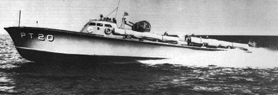
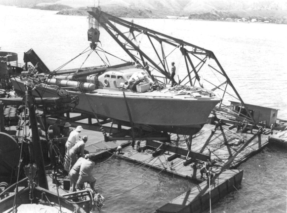
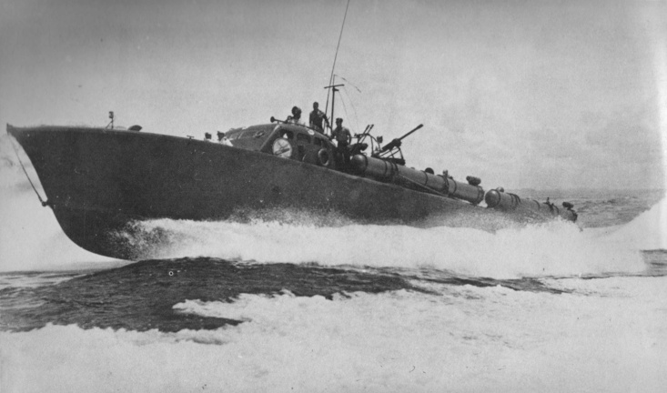
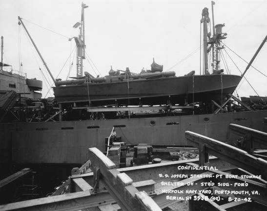
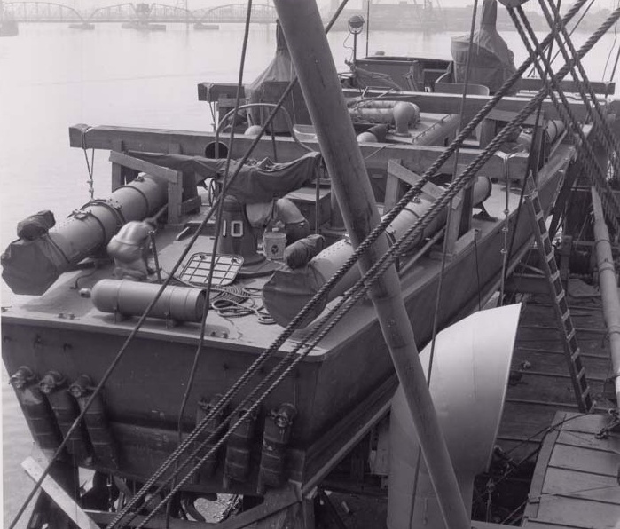
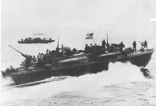
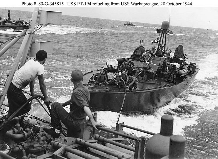
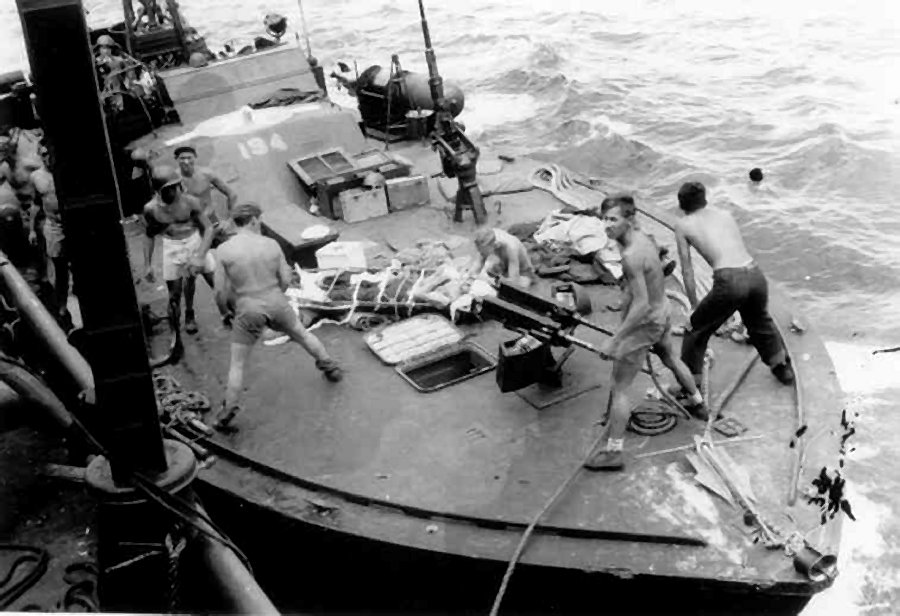
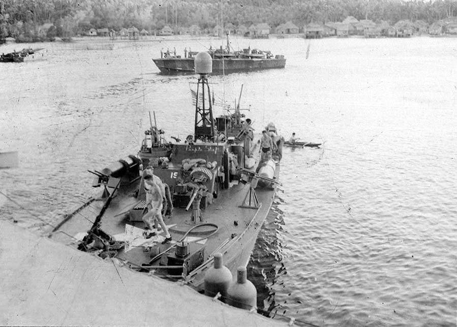
PT 109
PT 109 was an early 80 foot Elco Motor Torpedo Boat (class PT 103) completed and
delivered to the Navy in July of 1942. She was in RON 5 assigned initially to the
"Panama Sea Frontier" until transfer in September 1942 to RON 2. RON 2 had
six ELCO 77 foot boats and six ELCO 80 foot boats (PTs 109-114) and was shipped to the
Solomon Islands to participate in the defence of Guadalcanal.
In mid December 1942 five patrolling RON 2 PT boats engaged eleven Japanese destroyers northwest of Savo Island. The PTs torpedoed and sank Japanese destroyer Terutsuki, but lost PT 44 sunk by two destroyers off Savo Island. During January 1943 PT-109 engaged the Japanese as RON 2 boats continued action aganst the "Tokyo Express", and participated in shore attacks to destroy supplies already delivered on Guadalcanal. On the night of January 11 nine boats of RON 2 engaged eight Japanese destroyers and torpedoed one that did not sink. They lost PT 112 and PT 43 was damaged.
The night of February 1, 1943, twenty Japanese destroyers entered Iron Bottom Sound to evacuate the last remaining Japanese troops from Guadal canal. They were attacked by aircraft from Henderson field without significant damage and were then engaged by eleven PT boats. In the battle, PT 111 and PT 37 were sunk by Japanese gunfire and PT 123 by a Japanese float plane. PT 115 and PT 38 ran aground and were pulled off by PT 109. This was the final engagement between PT boats and "Tokyo Express" in Iron Bottom Sound as the Guadalcanal evacuation was completed in a week.
Over the next months, the action shifted to the more northern upper Solomon Islands as the Japanese reinforced their troops there. The PTs at Tulagi needed time for boat repairs and replacement of manpower. Lt. Westholm became operations officer for the flotilla and he was replaced by Ens. Bryant Larson and then by Ens. Leonard Thom, the executive officers of the boat. During this time the boats supported the invasion of the Russell Islands, part of the Solomon Island chain north of Guadalcanal.
Lieutenant (jg) John Fitzgerald Kennedy assumed command of PT 109 on the 24th of March, 1943, relieving Ens. Thom. In late April the PTs patrolled the Russell Islands more and in June some of the RON 2 boats moved to a more foreward base on Rendova Island, closer to the Russells.
A Japanese air raid on Rendova on August 1st sank PT 117 and damaged PT 164. That same night, fifteen PTs from the base went out in four groups to intercept enemy destroyers and landing craft reported moving from Bougainvile Island in their direction. In one group, PT 159 sighted and engaged the convoy and fired four torpedoes and PT 157 fired two, but they were driven off by heavy gunfire from the destroyers.
As the PTs fled with Japanese in pursuit, other boats were alerted to the battle by seeing searchlights and hearing gunfire and by radio messages from the boats that had attacked the convoy, but were uncertain as to where the action was taking place.
PT 109 in the meantime had rendezvoused with PT 162 and PT 169. They received radio orders from the base to resume their normal patrol stations. As they moved slowly at idle speet, they became separated. Nearby the Japanese destroyer Amagiri was returning from completing a supply mission and while running at nearly 30 knots, it rammed and sank PT 109, splitting the boat apart, throwing crew into the water and igniting gasoline spilled onto the water.
The forward half of PT 109 was still floating after the flames died down and Lieutenant Kennedy, Ensign Thom, Ensign George Ross, QM3 (Quarter Master Third Class) Edman Mauer, RM2 (Radioman Second Class) John Maguire and S1 (Seaman First Class) Raymond Albert all crawled back on board the hull. Three men were in the water to the southwest and two others to the southeast. These were QM3 (Quarter Master Third Class) Charles Harris, MoMM2 (Motor Machinist Mate Second Class) William Johnston, MoMM1 (Motor Machinist Mate First Class) Patrick McMahon - severely burned, TM2 (Torpedoman Second Class) Ray Starkey and MoMM1 (Motor Machinist Mate First Class) Gerald Zinser - also with burns.
Lieutenant Kennedy swam to the group of three, which included one man with serious burns and another with a water-logged kapok life jacket. Kennedy gave his life jacket to the second man and towed the burned man back to the floating wreckage, then swam back to help the remaining may back also. Meanwhile Ensigns Thom and Ross towed the other two survivors back to the floating section. Two sailors, TM2 (Torpedo Man Second Class) Andrew Kirksey and MoMM2 (Motor Machinist Mate Second Class) Harold Marney, were not located and presumed killed in the collision with Amagiri. They were probably below deck or directly killed in the impact.
In the early morning of 2 August all eleven survivors were clinging to the wreckage of PT-109 and it became obvious that the boat wreckage was going to sink. Kennedy decided to move the survivors to a small island some four miles southeast of Gizo, to avoid any Japanese. The sailors abandoned the bow and headed for tiny Plum Pudding Island, three and a half miles away. Kennedy, swimming the breast stroke, towed Seaman McMahon on his back, grasping the strap of the man's life jacket in his teeth. The nine other survivors swam together, holding onto a 2-by-8-foot plank from their boat. It took the 11 men four hours to reach the island. The crewmen, who later swam to a slightly larger island in search of food, were stranded for six days, living off coconuts, before they were rescued. At 1400, the crew pushed off for land, Kennedy towing the badly burned engineer and two non-swimmers clinging to a bamboo timber, probably one of the two used as a temporary mount for the scrounged 37mm Army anti-tank cannon the crew had installed on the fore deck before this mission. part of the 37mm gun mount. On shore, the group set up a temporary camp and hid.
Over the next few days, as their rations ran out, the men carefully investigated other nearby islands looking for food and trying to make contact with friendly natives. On August 5th, Kennedy used a canoe they had found to return to Ferguson Passage and scrounge food (coconuts) from nearby islands. In the meantime, two natives had happened upon the survivers and were eventually convinced by Ens. Thom and Kennedy to take a message to nearby coast watchers. A penciled note from Thom, and a message carved into a coconut husk by Kennedy.
.The next day, eight natives arrived with food, supplies, and a cook stove and instructions to take the senior officer to Wana Wana. Later that night Kennedy met with PT 157 in Ferguson Passage and with PT 171, guided by Kennedy and natives who knew the local reefs, the two PTs picked up the survivors, returning to Rendova by morning.
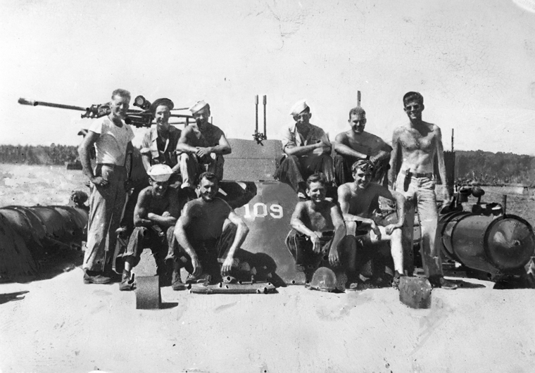
Crew of the PT-109. Back Row (L-R) Allan Webb, Leon Drawdy, Edgar Mauer, Edmund Drewitch, John Maguire, Lt. (jg) John F. Kennedy (standing, far right). Front Row (L-R) Charles Harris, Maurice Kowal, Andrew Kirksey, and Lenny Thom. Solomon Islands, 1943.
PT 109 crew on final mission.
Name and rate - Position
Lt. jg. John F. Kennedy - Commanding Officer
Ensign Leonard Jay Thom - Executive Officer
Ensign George Henry Robertson Ross* - Lookout / Gunner
S1C Edgar E. Mauer - Quartermaster, cook and signalman
RM2C John E. Maguire - Radioman
S1C Raymond Albert - Gunner
GM2C Charles A. Harris - Gunner
MOMM1C Gerald E. Zinser - Motor mechanic
MOMM1C Patrick Henry McMahon - Motor mechanic
MOMM2C Harold W. Marney (KIA) - Gunner
MOMM2C William Johnston - Gunner
TM2C Raymond L. Starkey - Torpedoman
TM2C Andrew Jackson Kirksey (KIA) Torpedoman
Notes:
* Not assigned to the PT-109 but went along on final mission.
Kennedy's original crew also included Maurice L. Kowal, Edmund T. Drewitch
and Leon E. Drawdy. All three of these men were injured on previous patrols
and were not on board when the PT-109 was sunk. Drewitch was injured on
June 30, 1943 when a depth charge was dislodged and came through the deck
landing on the bunk above him. Kowal and Drawdy were injured on July 19, 1943
by a Japanese aircraft attack. All these three men served under Kennedy later
on the PT-59.
The survivors received medical attention and most, including Kennedy, soon returned to active duty. Kennedy requested and received command of the PT 59 and supervised her conversion to a gun boat, described in more detail below. Most of the surviving crew volunteered to go with Kennedy to the PT 59.
Kennedy kept in touch with the PT 109 crew through the rest of his life. Crew were invited to his Presidential Inauguration and those who could make it, rode on a float with a replica of PT 109 in the inaugural parade.
I never met any of the 109 crew personally. Those living in Massachusetts remained active with the PT boat Museum there. In a conversation with the director of the museum about Kennedy and the 109 crew, I was told that the crew remained entirely devoted to Kennedy and would say only that "you don't know the half of it" when asked about Kennedy's heroism during the sinking and the survival.
Notes on crew of PT 109
Leonard J. Thom was born September 8, 1917 in Sandusky, Ohio. He was the executive officer of the PT-109 under Lt. Bryant L. Larson and served as commanding officer for the period of time between Lt. Larson's departure and Lt. jg. Kennedy's arrival. He was then assigned as commanding officer of PT-587 and later returned serve at the PT training base at Melville, Rhode Island, and attended a PT 109 crew reuinion at the Kennedy compound in Hyannis, Massachusetts in 1944. He was killed in a car accident on October 8, 1946.
George H.R. "Barney" Ross was born in 1914 in St. Louis, Missouri.
After the war, he went into the insurance business in Illinois
and in 1959 Senator Kennedy asked him to help him in his campaign
for the Democratic Presidential nomination.
After Senator Kennedy was elected President, he named
Mr. Ross to the President's Committee on Juvenile
Delinquency and Youth Crime. Mr. Ross also helped
draft proposals for the Peace Corps and Vista. He
relocated to Bethesda, Maryland.
Ross died July 24, 1983 after a heart attack.
Edman Edgar Mauer
born 26 Aug 1914, St. Louis City, Missouri
died 22 Sep 1974
also served on pT 59
Raymond Albert born died Raymond Albert,from Akron, Ohio, was twenty years old when he joined the crew of the PT-109. After surviving the sinking and the rescue of the crew, he returned to duty and served on PT 163, where he was killed on October 8, 1943 by a Japanese POW, one of a group of Japanese sailors that had been rescued by the PT from the sinking of the Japanese destroyer Yugomo.
Charles A. "Bucky" Harris was born 28 Sep 1922 in
Watertown, Massachusetts.
He died 6 May 1982 (aged 59) in Waltham, Massachusetts.
Charles A. Harris from Watertown, Massachusetts was twenty when he joined the PT-109 and
was part of the original crew when JFK took command of PT-109 at Rendova, Solomon Islands.
He was off duty sleeping on the deck near a torpedo tube at the time of the sinking of
PT 109 and awoke just as the Amagiri hit the PT-109. He dove but injured his leg and
was found with Edgar McMahon and guided back to the bow wreckage of the boat by Kennedy.
William Johnston was born around 1910 in Scotland. He died 5 Jul 1968 (aged 57–58) in Seabrook Beach, New Hampshire, USA
Andrew Jackson Kirksey was born 5 Nov 1917 and died in the sinking of PT 109 on 2 Aug 1943 (aged 25)
Harold William Marney was born 25 Oct 1924 in Springfield, Massachusetts,and died in the sinking of PT 109 on 2 Aug 1943 (aged 18)
Ray Lee Starkey was born 2 Feb 1914 in California and died 8 Oct 1970 (aged 56)
in Anaheim, California.
He was an Oil Worker for Signal Oil Co. in Huntington Beach, CA, and
was the Chairman for "Kennedy in Garden Grove" during Kennedy's 1960
presidential campaign.
Maurice L Kowal, born 15 May 1922, Massachusetts, died 30 Oct 2011 (aged 89) was the last surviving crewman who had served on the 109, although he was not on board at the time of the sinking. He volunteered to serve under Kennedy again on the PT 59. When he became President, JFK appointed him to a position in the National Park Service.
Edmund T. Drewitch, age 30, was the sixth man on the crew for PT 109 that Kennedy was assembling. He joined the crew on the day Jack took command. He was age 30.
Leon Emery Drawdy born 3 Jun 1913 in Saint Cloud, Florida, died 12 Nov 1962 (aged 49) in Orange County, Florida.
The last survivor of the sinking, Gerald Zinser, died August 22, 2001. He was
the only career Navy man on the crew and served a total of 20 years
in the Navy. He is quoted as saying in 1994 I served 20 years in
the Navy and I never had an officer that would ever come
close to what I saw Kennedy do.
The crew of the PT 109, when John F. Kennedy was skipper, also experimented with added guns. At the time of her sinking, she was carrying a 37mm army field piece on the foredeck. The crew had removed the wheels from the trailable gun and lashed it to two timbers on the foredeck. It was one of those timbers that broke free at the sinking and provided a flotation device for the injured crew. The boat was also carrying added depth charges along the side of the foredeck. If the 109 had been equipped with radar, she would not likely have been hit and sunk by the destroyer. The PT 59 had an early version of the radar that later became standard on PT boats. What a difference a few weeks makes.
PT 59 was sompleted 5 March 1942 and initially assigned to Motor Torpedo Boat Squadron FOUR (RON 4)
the training squadron, based at the Training Center, Melville, Rhode Island, before being
transferred in May 1942 to Motor Torpedo Boat Squadron TWO (RON 2) and late in 1942,
RON 2 with six 77' Elco boats and six 80' Elco boats, was shipped to the South Pacific.
where it was active in the Solomons campaign, engaging in many night actions with the
Tokyo Express in the defense of Guadalcanal. The reconstituted RON 3 also operated in the
Solomons, having arrived shortly before RON 2, and later PT 59 was transferred to RON 3(2).
PT 59 "Barge Buster" Gunship, 1943
The supply barges became the PTs primary target but the armor on the heavier barges was impervious to gunfire from the PTs. The leadership of the PT operations decided to experiment with mounting heavier cannon on PT boats. Some crews had already experimented using salvaged 37 mm auto cannons from damaged Army Air Force P-39 aircraft and these were better against the barges, but crews wanted something even heavier. The decision was made to strip PT 59, PT 60, and PT 61 of torpedo tubes and mount single 40 mm Bofors cannons on the bow and stern of these boats together with additional 50 caliber machine guns along the sides where the torpedo tubes had been. The additional machine guns were to be used as suppressive fire against the barge crews, while the 40 mm cannon were used against the barges. The Bofors cannon fired a variety of shells including high explosive and armor piercing variants. The shells were in clips of four, and each gun required a crew of four to operate it: two gunners, one loader to put the clips in the gun, and a second loader to bring ammunition to the loader. Under optimum conditions, the gun had a rate of fire from 120 to 140 rounds per minute. The Bofors 40 mm gun proved effective against the barges, and soon one of these guns became standard equipment for PT boats mounted on the after deck, even on PT boats that still carried torpedoes.
After the sinking of the PT 109, Lt. John Kennedy requested another command. At the time, he had multiple medical issues, including a re-activation of a long standing back problem as well as the dysentery and other tropical diseases that affected most of the men on Rendova. He was given command of the PT 59, due to be converted to a gunboat. Kennedy supervised the conversion and skippered the boat until late November of 1943 when his medical conditions mandated his return to the U.S. By this time, he had lost over 40 pounds. At six feet tall, he weighed 145 pounds.
Kennedy supervised the refit of the PT 59 and in addition to the added guns, he installed armor along the sides to protect the gas tanks.
Members of the crew of the PT 109 who were fit for duty were offered the opportunity to volunteer to serve on PT 59 under Kennedy, and five did, including three men who had been injured earlier and had not been aboard on her final voyage.
PT 59 in October along with other boats was tranferred to another advance base, Lambu Lambu, on Vella Lavella Island in the northern Solomons. In early November of 1943, word came that some Marines that had landed on Choiseul Island had met heavy resistance, were trapped, and needed immediate rescue. The PT 59 was one of the boats at Vella Lavella available for the mission, but had just returned to base and had not yet refueled. Kennedy approached his crew and explained that they had enough fuel to get to the island, which was 70 miles away, but not enough to get back and asked them to decide if PT 59 should go. The crew voted yes, and the boat headed out with fuel enough to get there and a tow rope for a sister boat to tow them back. Choiseul Island, in the northern part of the Solomons, was close to Bougainville Island, part of Papua New Guinea. It was about 100 miles from the Rendova PT base.
Because Kennedy's boat lacked the fuel for the return trip, PT 236 accompanied her. PT-59 arrived at a Marine outpost at Voza Village and picked up Lieutenant Richard Keresey, and Lt. Col. Krulak, to guide the boat to the trapped Marines. PT 59 arrived after dark in the rain at the Warrior River site and assisted landing craft evacuating the Marines. They were able to rescue about 40 - 50 Marines of the 90 who originally landed at the site. Some of the Marines were wounded and some came from a Marine Parachute Regiment that had been lost in the jungle and trapped by Japanese fire during a recent raid on Choiseul Island. Kennedy did not have his gunners fire on shore while the Marines were waiting to evacuate so he used the boat a shield between Japanese shore guns and the Marines in the water. One landing craft had been damage and PT 59 took aboard ten Marines from that vessel. Three were wounded and one, Corporal Schnell died in Kennedy's bunk that night.
The two PT's, including Kennedy's, then escorted the slow-moving landing craft to a Marine base then returned to the PT base at Lambu Lambu. Around 2 AM that night, PT 59 ran out of fuel and was taken in tow by PT 236. On the evening of 3 November, PT-59 and four PTs traveled around 45 miles from Lambu Lambu back to the Marine base at Voza Village and escorted several landing craft carrying Marines back to Vella Lavella Island.
Over the next weeks PT 59 returned repeatedly to damage or destroy Japanese barges around Choiseul Island. In November PT 59 took part in thirteen patrols, to discourage Japanese barge traffic in the north of Choiseul Island.
Kennedy was sent to the U.S. on medical leave in late November.
PT-59 remained in the Solomons until August 1944, when she and five other 77-ft Elco PT boats, including PT-36 and PT-47 were transported back to the PT Boat Training Center in Melville, Rhode Island. In October 1944, she was reclassified as a "Small Boat" and renumbered C102583. Along with the former PT-47 also now a Small Boat, she was used briefly as a crash rescue boat at the Naval Station in Norfolk, before being transferred to the Philadelphia Navy Yard in December 1944 to serve as subjects for dehydration and preservation testing.
PT 59 was surveyed on 21 March 1947, then she was stricken and sold to Captain Gus Marinak of Bronx, NY, re-named "Sun Tan" and used for fishing and excursions. She was later sold to Captain Donald Schmahl of New York and renamed "Sea Queen V" to be operated as an excursion boat in the New York City area.
PT-59 quietly ended her days in the 1970s after some years as a fishing boat. Because the boat was erroneously thought to be the former PT-95, a 78-foot Huckins PT boat, no efforts were made to save or salvage her. The actual PT-95 had been scrapped in 1945. When the real identity of this fishing boat was discovered, James "Boat" Newberry, founder of PT Boats Inc., attempted to obtain her but ownership was tangled up in the NYC probate court and never completed.She ended her days as an unpowered houseboat and after an electrical fire, the boat sunk at its moorings, beside the 207th St. Bridge over the Harlem River, around 1976. The hull sat for years at the bottom of the river and slowly rotted away.
In 2017 efforts were made to locate the remnants of the boat but funding was lacking. In 2020, the Manhattan Metropolitan Transit Authority found portions of the boat when excavating to replace a sea wall. The wreckage was beneath about eight feet of mud and sand and included all propeller shafts and hull penetrations, struts, one propeller, rudders, and the port side aft rear corner. The wooden remains include only the lower areas of the engine room and stern. What remains of PT 59 was tranferred to the PT Boat Museum at Battleship Cove in Fall River, Massachusetts, where they are on display in a preservation tank at a new PT 59 exhibit, opened in 2022.
Below are two pictures of PT 59 as she arrrived in the U.S., probably at New York in transit to Melville.
And there is one picture of the burned wreckage of the 59 at her mooring where she burned around 1976. And a picture of her as JFK's second command, PT 59 "Gunboat".